Showing posts with label CAD Design. Show all posts

Thursday, June 23, 2022

36ft Fowler Boxcars - NC&StL 15337 (Part 1) Accurail Kitbash

Back in 2018 I picked up one of the new Accurail 36ft Fowler boxcars.  I already knew these cars were not seen in uncommonly large numbers on the Tehachapi Pass area. 

NC&StL 15337 kitbash coming together

So I decided I'd get one of the new models to add to my 'signature car' fleet.  This group of cars I've been working on generally follow Ted Culotta's RMC articles years ago with the same name.  Generally, these are unique and easily identifiable cars that did show up regularly around the US. 


These include cars such as; "WWII Emergency" Boxcar, NP "Double-Sheath" boxcar, Milwaukee "Rib Side" boxcar, B&O "Wagon-top" boxcar, PRR X29 boxcar and NYC "Standard" boxcars just to name a few.  I believe all of these could show up on the Jawbone from time to time

The only one that I found at a local hobby shop was a painted "Data-Oxide" version.  I'd already been doing some digging on-line, and I'd found several great research pages which explain what needs to be done to the Accurail model to make it more accurate for specific RR prototypes.

Around the same time, I'd also picked up a Westerfield Undec CP/Soo Line version of the Fowler car with a 5ft door cheap at a convention.  I'd also picked up a couple more Canadian car kits to build at some point, including a CP 'Mini-Box' which is an all-steel boxcar with a small 5ft wide door.  I also already had an Accurail USRA-clone CN single-sheath 40ft boxcar. 

Prototype History


I basically have the choice to model one of the following prototypes: CN, CP, Soo Line, or NC&StL. 


But for now, I'll see what this Accurail model can be turned into.  The Accurail model only works for 6ft door cars, so all CP cars are out, along with the Soo Line cars, but the Soo Line cars might work for my Westerfield resin car.

Crunched data based on Rey Breyer's Fowler article.

Based on the research from the above links, CN and CP certainly would be the largest fleet owner.  Both used the majority of their Fowlers in the grain movements within Canada.  Some of the linked photos in the above articles show one CP car with a tare date of 1952 still fitted with K-brakes and arch-bar trucks!  The arch-bar trucks were banned in interchange service by the ICC in 1940.  So I selected NC&StL, as one of the more accurate kitbashable models to make from the Accurail model.  There were still several hundred of these cars in service in 1950, and I don't have any NC&StL boxcars in my fleet for the Jawbone Branch.

The most likely finish the Westerfield resin model as a CP car for these cars would be bringing Canadian grain down into the US.  Cars in that service would probably be returned empty to Canada by reverse route, as there were Service Car Orders (SCOs) in place after the Canadian Railroads complained that too many of their cars were not making their way back to Canadian rails in any fashion of a timely manor.

Starting My Model


Basic Construction


Stock Accurail kit with the box slightly shaken.

I didn't really do anything special to the basic kit so far.  Here's the basic body and underframe assembled roughly in 2019.  Much has happened in my life since then, so it's nice to open a 'basic kit' up again and do some kitbashing.

Roof Modifications


The CN cars received replacement metal roofs by my modeling era of 1946-1954.


I'm starting into the roof modifications by removing all the running board supports.  Easily done with a chisel blade and carving them off.  The corner grabs are also shaved down and removed.  I'm not worried about re-scribing the board detail as all of that will be sanded off.


About an hour of sanding and filing later I'm getting the roof cleaned down.  - I'm going to pause here to deal with the underframe and weight.

Weighting the Floor


 Kadee 'whisker', 'scale head' 158 couplers installed with the stock draft gear boxes.  At this point in the build, I was thinking about doing the conversion to make a CN car, but eventually I decided to shift to NC&StL prototype.


Floor interior is scribed to help the RTV Silicone grip the plastic floor. 


Clear RTV Silicon applied to interior of the floor and weight ready to apply.


Weight applied to Silicone and waiting for it to dry.  OK, back to sanding the roof!

Continuing Roof Modification


Roof is finally sanded down smooth, removing the wooden roof details of the stock model.

A quick CAD calculation of the new metal roof spacing for the joint covers.

The end ribs are made by 0.100"x0.020" styrene strips.  The narrow ribs are 2"x4" scale styrene strips.


Styrene strips are applied starting at the end with 0.100" x 0.020" strip and the first of the standard joint cover ribs from scale 2" x 4" strip.


Following ribs are marked with my Tichy boxcar weight bar used as a spacing tool for my pencil marks.


Double checking the exact spacing with my calipers.  Trimming to length with my sprue cutters after the Tamiya liquid glue to dry.


Completed roof ribs all glued in place.  I knocked down the edges of the ribs at the roof edge with a stroke or two of fine sand pad.


The running board was inserted into the four holes in the roof and additional bits of 2x4 strips were slipped under to create the supports.  The supports were cut to length with a No.17 chisel blade, and then Tamiya glue was applied with the brush applicator.  The body was then inverted and the running board was then pressed onto my flat working surface to compress the arch out of the 2x4 pieces and get them to adjust to resting over the peak of the roof.  This process worked well, but it was best to do no more than about two supports at a time, then pressing, and then continuing.

AB Brake Conversion


The NC&StL car that I'm basing my model on was upgraded with AB Brakes and U-section AAR trucks.


I cut the K-brake in half, removing the reservoir section.  New AB reservoir and triple valve were taken from one of my Accurail 40ft USRA-clone boxcars, (which will become an SP B-50-8/10/11-series car).


New brackets and mounting pads were fabricated from styrene strips.

U-Section Trucks


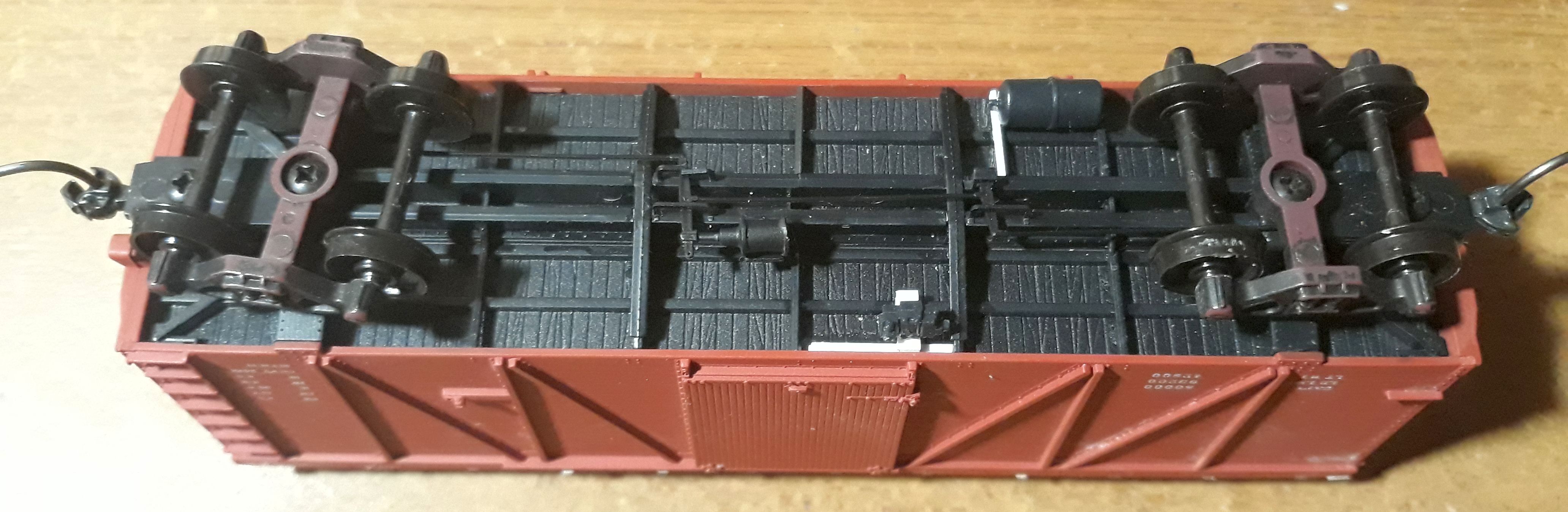
I've also changed out the Accurail Andrews trucks to some second hand Athearn-MDC heavy U-section AAR trucks, which are similar to the trucks in the photo of the NC&StL prototype.  

In Closing


The NC&StL 15337 kitbash coming together as of 2022-06-20.

Stirrup steps still need to be applied.  I did pick up a set of CP decals for the Fowler resin kit when I checked with Andrew this week.  So I'll probably do more on the CP Fowler and other cars while waiting for Westerfield to re-run the NC&StL Fowler decals..

Jason Hill

Related Articles:


Monday, March 29, 2021

SP Jawbone Branch (Part 19) - Owenyo #1 Secondary Bracing & Wye

The last three (SP Jawbone Branch Part 16, Part 17, & Part 18) blog posts have been on the structural aspects of the modules.  Now I'm moving on to the next phase of construction as I wrap up the last of the secondary bracing.

Plan for the underside of Owenyo #1 module

One of the advantages of drawing the structural details on my CAD models is that for several months I've already been visualizing what the structure will look like.

Secondary Diagonal Bracing


Special cut corner 2x2 blocks to accept the secondary diagonal bracing.

Following the same style of diagonal bracing from the Owenyo #2 module and the two staging modules of Mojave Yard, the more complicated Owenyo #1 module mixes diagonal bracing into the heavier support structure for the removable wye.

West end of Owenyo #1 module with diagonal bracing and front edge fascia dry fitted.

The west end of the module is mostly just needing the diagonal bracing installed.  Corner supports for the two diagonals along the front edge are still needed.

East end of Owenyo #1 module with the two "Pits" cookie-cuttered and bent down.

The edges of the Narrow Gauge "Pit" are cut longer and also relieved back, which will have the foam glued in from the bottom to create the slopes.

Finishing the Primary Wye Supports


Wye Issues?


Wye structural support "Keel" or spar.

Without the diagonal truss bracing the module was able to twist when I put a little force down on the tail of the wye spar/keel.  However with the secondary bracing installed the module does not twist anymore.  When force is applied to the top of the wye now tries to lift the whole rear edge of the Owenyo #1 module.  I'll probably still make a bracket or clip to hold the back edge down near the center focal point of the wye bracing.

Sistering & Supporting Front Frame & Wye "Keel"


The last two major structural support elements need to be installed before I can start working on the wye or moving forward with the rest of the construction.

I sistered up the front frame with 2x2s to provide a good anchor point for the lower plate.

This is the rather nightmarish structure to support the removable wye module as a cantilever.

Intermediate 3/4" plywood shims for the support of the wye and front frame.

A layer of 3/4" Plywood is needed to build up the depth to match the oak wye 'keel'.  The two triangles were also thinned to make a shelf, matching the two heavy diagonal frames.

Here's the intermediate cover plate marked to be cut.

I cut the two triangular sections to anchor to the front plate of the wye.  My table saw makes short work of this joint work.  The 2x2 riser cutout is made with a saber saw.

I cut a slot in the intermediate cover plate.

I don't want to cut any more height off the wye's structural keel than I need to.  I cut away two plies of the 3/4" plate.  The right side I also cut away the profile of the 2x2 riser.

The wye tail thinned to match the intermediate cover plate slot.

The cover plate is also 3/4" plywood with the same 2x2 notch cut for the riser.  The intermediate plate layer is glued in place.  

Lower cover plate.

I marked out the four support areas under the plate where I will attach it with screws.  Before I screwed this cover plate in place, I decided that a couple of holes should be added to lighten the module and also to provide some good handles!

Here's the wye 'keel spar' in place along with the 2x2 riser.

The front edge of the layout is definitely heavier now with all this box structure assembled.  Time to test it and see if my balance issue is still a problem.

The cover plate screwed in place with the keel-spar in place as well.

Well, with the module in place it definitely takes very little down-force on the tail of the wye to lift the back edge of the module across the 2x2 riser.  Time to build a bracket to hold it down back there!

Wall Bracket Hold-Down


A couple of scraps thrown together to make a bracket.

I decided the quickest and easiest way to build a bracket for the back of the Owenyo #1 module was to take a chunk of 3/4" ply and a small scrap of 1/4" MDF frame material rem, glue them together.  Then glue and clamp to the back of the module's frame.  (Yes, I'll have to grind off the tips of those two screws, OUCH!)

Hold-down bracket installed.

The module is now secured to the wall and can't rock if an engine heads out onto the wye.  I'll just have to remember to remove these two screws in the wall-bracket when I want to take this module down to work on.  Not a big deal really.

In Closing


Jawbone Branch coming together.

The next step is getting the holes drilled for the alignment pins and bolts.  Then track?  Hope so!

Jason Hill

Related Articles:


SP "Jawbone" Branch Index Page - Links to all my blog posts on my new Jawbone Branch layout.

Thursday, March 18, 2021

SP Jawbone Branch (Part 17) - Upgrading Bracing, Mojave Structure & Foam

This post is a quick follow-up to SP Jawbone Branch (Part 16) which mostly covered the more complex Owenyo #1 structure and the brackets used to hold up the south side of the layout.  I realized that I haven't really posted photos of the upgraded basic structural system within the modules themselves.

Owenyo #2 with bracing removed

My first implementation of the bracing under the standard modules was with mitered and glued joints, which several of my friends who I consult with expressed concerns about.  After I've built the stronger version of this structure used on Mojave West and Middle panels with 2x2 corner blocks which were cut to accept the braces showed a much better strength, I planned to knock out any braces that were not firmly attached on Owenyo #2 panel and upgrade the installation.

New 2x2 corner blocks cut and slotted for installation.

I used the table saw with additional 3/4" ply shim to move the 2x2 blocks being cut to the proper location over the angled blade.  Definitely use the plastic push handle to guide the lower part of the block through the saw.  I was very carefully holding the upper corner of the block, but sure that I was not pushing into the blade if the block kicked out of the saw.  I want to keep all 8 fingers and 2 thumbs for many more years!


The other main change I made with this upgrade, which I planned to do before I actually glued them, was to thin the braces to only 1" from the edge thickness of 1.75".  

The new braces are all test fitted before glue is applied.  A small hammer is used with a scrap piece of MDF preventing damage to the edge of the MDF braces.  Clamps are used to hold the 2x2 blocks in place while the glue dries.

Cutout for the foam scenery insert in Owenyo #2.

The thinned diagonal braces are shown here.  I broke the edges of the MDF with a rasp.  Many future cuts will be prevented by doing this.

Here's the "tunnel view" of the Mojave Staging Yard with Owenyo #2 module above.

In the above photo, notice the reduced height of the bracing.  This is the upgrade which I planned so that my knuckles don't get killed reaching into the staging yard!  The stack distance at the front edge is only 4", but it's now 4.75" to 5.75" in the interior space above the staging yard.  I know the track will raise the equipment a few fractions of an inch, but the new space should more than make up for that.

Middle Mojave Staging

The last of the plain panels to build is the "Mid-Mojave" panel.

Diagonal EF and FG installed with new square braces at E and F on Mid-Mojave

The blocks are marked A, B, C, etc to show where on the panel they go.  The diagonal braces are also marked AB, BC, etc to show where they go, as each is cut to fit.

Mid Mojave panel with diagonal braces prepped.

I used some of the wider strips to make the bracing under Mojave, as it will not be needing the same type of tight access.

Large Clamps used on the five square cross braces at the west end of the Mid-Mojave panel

This one used Tight-Bond II wood glue and was quickly assembled with the large clamps spanning over the square braces and the smaller clamps holding the 2x2 blocks in place while the glue sets.

Middle of the panel clamped and glued.

At some of the corner blocks I have added pieces of 1/4" MDF to fill the slots or wedge the braces to exact length.

Eastern end of the Mid-Mojave panel

I may decide to add a couple of support blocks where the black marks are on the front and rear frame rails where they cross the wall bracket arms.  While the layout seems strong now, it may be better to bulk up these areas to help spread the vertical loading on an area wider than 1/4".

Underside of Mojave Middle Staging Yard panel looking east towards ladder.

This workbench area under the staging yard will be used as before.  The 13" clearance should be enough for my regular use of the space.  I have a light-table and other low profile items planned for this area.

Mojave Middle Staging Yard panel looking west towards West Mojave panel.

The panels are sitting pretty well with the wall brackets supporting them.

Owenyo #2 - Breaking Up the Plywood (MDF) Pacific


Many years ago layouts which were simply sheets of plywood with no dramatic scenic features were dubbed the "Plywood Pacific".  To break up the same syndrome settling in at Owenyo, a couple weeks ago I started making some changes to the western end of Owenyo #2 Module by cutting out a section to start the contouring terrain.  The land form change needs to start in #2 module because in the middle of the curve in #3 module, just west of here, there's a timber culvert under the main track that will need some place to drain.

Sketch of how the terrain falls away from the west switches in Owenyo.

This is also the first section of the layout that needs to start transitioning to 'cookie-cutter' benchwork and roadbed style to mate with the planned Owenyo #3 corner module  The construction of the Owenyo #3 module will be a full hybrid of MDF and Expanded Styrene Foam for the land forms and the 'High Line' NG trestle pit for the SG track buried down into the surrounding foam.  

The opening in the MDF cut for the foam insert.

I cut the top sheet of MDF with the table saw and then flipped the module on its edge to cut the corner.  These cuts allowed me to get the saber saw blade inside of the structural frame of the module to do the rest of the cutting.  I had some rough Sharpie marker paths to follow, but basically free-handed the actual cutting with the saw.  The edge was then finished a bit with a rasp to knock off any sharp edges.

CAD plan for Owenyo #3 with the "High Line" Trestle over the SG pit.

The grade down towards Mojave as soon as I can, possibly just west of the end of the Owenyo #2 module, as soon as I can make the vertical easement to the 1.5% down grade.  One of my major gripes with trackwork in general is not having proper vertical curves transitioning between different grades.  This can lead to vertical uncoupling on longer cars and engines.  Starting the transition to the grade earlier will also help with the SG pit track "dive" under the NG transfer trestle by cutting the vertical distance the spur will need to drop. 

Here's the view of the foam block cut out.

I cut the foam 5.5" wide and 20.875" long.  One corner had to be cut off to mate against the diagonal brace inside the module.  This will cut the available "hand space" to only what is below the diagonal rib in this area, but that should still be sufficient for my needs.

Dry-fitting of the foam block.

Always be sure to test fit pieces before putting the sticky gooy stuff on the pieces!  The piece was actually a good snug fit against the diagonal brace and west end-plate of the structure.

Gorilla Glue applied and a couple of the clamps in place.

Gorilla Glue expands up to four times its starting volume... so be sure to clamp the pieces of material together.  Also expect drips from the bottom as it pushes out extra glue!

I clamped both ends, and eventually two places front-to-back.  Two wedges were pulled together from rem's to support the bottom of the foam, which pushed against the Mojave Staging level below.  Two gallon jugs were placed on top of the MDF roadbed to keep the glue from buckling the roadbed upwards.

View of the module after the glue has expanded and dried.

The glue dried and did stick one piece of foam that I put under the right edge vertical clamp... so a few bits of white pop-corn foam are now stuck to the underside of the purple foam, oh well.

Eventually I'll probably do some forming of the foam down towards the profile I randomly cut in the MDF frame and blend it up to the MDF roadbed.  I was sure to leave enough MDF roadbed to mount the headblocks of the switches.  I could probably also rasp down the edge of the MDF as well, reducing the amount of 'fill' material I'll need to use over the foam area.  I guess we'll find out in a future installment!

What's Next?...


This post pretty well catches the blog up on where the layout is as of the 18th of March, 2021.  I'm looking forward to getting some track soon.  The next sections of construction without the track needs to be pointed at the three following areas:

  1. Decide on the alignment pins and bolt system to connect the modules, then actually build the jig and put the critical holes in the structurally finished sections of the layout. (Yikes!)
  2. Continue construction of the secondary structure under Owenyo #1 and push the structural support for the "removable wye and keel".
  3. Start construction of the Owenyo #3 module which will be a full hybrid of MDF and Expanded Styrene Foam plus a grade transition and the footings for the 200ft long transfer trestle!


In my CAD plan I start the grade as the track "rolls over" the edge of the grade just below the culvert.

This slight design change from how I quickly mocked the plan up in the computer should allow me to increase the length of the 1.5% grade and there by the vertical distance which I'll be able to get by the time the track reaches Mojave Staging below Owenyo.  

My rough 3D CAD model of the whole layout.

The CAD model shows about 5" and some change for a 1.5% grade, but that's with very conservative starting and ending points for the grade.  If I can extend the grade back nearly to the west switch at Owenyo and possibly even through the curved lead into the staging yard at Mojave, then I'll probably get at least another 3/4" of height (Edit: max of 1.2" assuming the following is true).  I've run the numbers again, a possible grade run of 480" and a climb of 6" results in an average grade of only 1.25%.  This gives me 0.25% to play with in terms of vertical easements and fudge-factor if I've made a mistake in my calculations.  I'd rather have a longer grade run and a slightly lower grade, just averaging the total climb over the whole path around the west, north, and east walls of the room.

I guess I've had enough 'simple' shown in these last two posts.  Nothing will be 'simple' from here on!  However, I'm not too worried about the next sets of challenge which await me.  The two small pits in Owenyo #1 module has let me see how the 1/4" MDF will respond to flexing.  Also the inserting of the foam and gluing to Owenyo #2 module has let me play with Luke Towan's MDF Frame and Foam Center construction method in practice.  I must say that it is very strong with the Gorilla Glue being used and properly clamped during drying.

3D CAD model of the structure I plan use building the Owenyo #3 module.

So I'm looking forward to changing from the simple 'box' construction of the first four panels and into the hybrid construction of the new section from a couple of road bed pieces, structural rails of MDF and precision cut foam sections glued in place filling up the sections in between.

In Closing


Stay tuned as I continue the construction of the SP's Jawbone Branch in HO scale.

Jason Hill

Related Articles:


SP Jawbone Branch (Part 16) - Brackets, Pits & Diagonal Joints - Construction of modules, supports, etc.

Jawbone Branch Index Page - List of all my SP Jawbone Branch modeling posts