Sunday, May 16, 2021

SP Jawbone Branch (Part 27) - Finishing Up East Owenyo Switches

Time for a "catch-up" post on how the Jawbone Branch is coming along.  East Owenyo is coming right along.

A normal viewing angle of the east switches at Owenyo as of this update.

Yes, I've been laying the switches and spiking them in place.  I need to do a little more final spiking here and there, but the track's all in gauge now and the cars can roll through the spiked over switch throw bars. 

Here's a low view of the east Owenyo switches before I put in the points and closure rails.

Here's about how the east end of Owenyo looked at the end of Part 23, where I started to cover the switch components and laying out the ties.  The stock rails are in place, setting up the frame work for the closure rails and points to be put in place.

Points & Throw-Bars


Following LMRC standard, we cut out the roadbed which will be covered by the throw-bar.  This is nice to do so the 1/4" long 00-90 screws can just be fed through the throw-bar and not foul the movement of the switch on the roadbed.

Dremal out the area between the rails, headblock and 1st tie.

I'm using some temporary throw-bars, and plan to have some new ones CNC'd soon.  Some how my drawing from 8 years ago changed and we drilled the new batch with the holes in the wrong spot... Oops!  So, time to triple measure this time before making powder. 
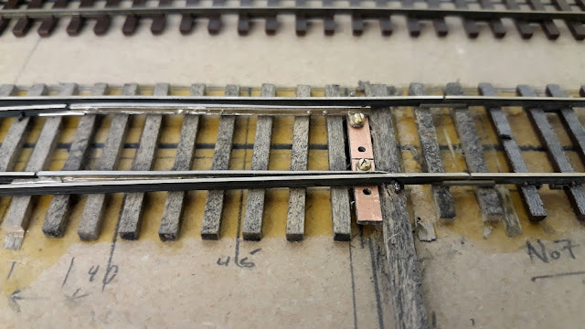
A close-up view of the switch points and a temporary throw-bar made from PC board.

These are proof's I hand drilled the holes and changed to club standard 00-90 screw thread.  I don't know why, but the new DTW instructions say to use 0-80 screws and give tap drill info to do that.  The 0-80s I could find have WAY too high and wide of heads to work.

Point Drill Jig


I made a jig out of scrap MDF to drill the throw-bar clearance screw holes.

The points all need to be drilled for the 00-90 screws.  While the white-brass point castings are stronger than the white metal guards, I feel that the support of the wood strips will keep them from the risk of getting bent or catching on the drill bit, spinning out of my grasp as the bit breaks through.

Switch Progress


The switches are now pretty much done, alignment-wise.

A high-angle shot of the east switch complex at Owenyo.  All the points are in, closure rails.  I'm still working on the exact method I'll be using for the switch mechanism.  The LMRC club uses PFM switch machines, long out-of-production.  So I'm looking at basic manual-mechanical options with a micro switch for the frog contact.  I'll probably build a couple mock-ups to test and standardize my design before doing any modifications to the layout structure.
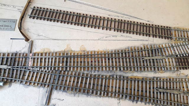
Here's a part-way progress view of the closure rails, points and throw-bars going in.

Hopefully this photo will show better the details as I was laying the closure rails and points in.  This process actually went very fast.  I think I did the whole east end in one longer evening.  I stopped just short of doing the switch the transfer pit at the top of this photo.  

SG-NG Equipment Transfer Ramp/Pit Switch


SG switch to the end-to-end SG-NG equipment transfer ramp/pit.

That switch and adjusting the alignment through the 3/4 right hand No.5 wye switch took a bit of time the next evening to get the gauge right and with a good flow through both routes.  Yes, it looks like a standard No.5 RH switch, but the left side is actually also changing alignment to meet the main track at a No.7 alignment and the diverging right hand route is more along the line of a No.6 or so, thus the No.5 frog angle works out.  Just west of the headblock is one of the angled transfer platforms, so everything is rather tight here.  Selective compression strikes again!

I'll be covering more on this spur in an upcoming post dealing with the NG trestle to get the equipment up on top of the SG flatcars.

Switch to House Pocket Stub


The little stub spur pocket No.5 switch between the "perlite" loader and the stock transfer pen.

I still need to finish up this No.5 switch off the middle of the house track.  This track needed shortening.  Somewhere along my early measurements of the room, it showed about 3" longer between the doors.  I'm not exactly sure how that error crept in, but I know the wall is about 3" shorter than my original CAD drawings!  So I've shortened the spur a bit, and will also want to move the stock transfer platform slightly east and/or shorten it a bit too.  This should allow me to move the west switches of Owenyo east enough to account for the shorter space.  Changing this switch to a No.5 alignment definitely also helped!

West Wye Switch


West switch of the Owenyo wye is basically a No.5 frog with a long point alignment.

The wye's west switch is basically the easement coming out of the 26" radius wye curve, which stretches out the points towards the length of a No.7 switch.  I went ahead and installed the DTW white metal guard rails.  LMRC standard is to fabricate (bend) up rails and hold them with spikes until they can be tack soldered at the two ends.  I'm going to try the DTW guards and see how they hold up.  The white metal is very soft.

A more normal viewing angle of the east switches at Owenyo.

I drilled holes at each end of the temporary throw-bars and spiked the switches in place, so I can check the operations through that route.  I'll have to keep doing this method until I get the switch mechanisms up and working. - Plenty of things still to do!

Next Steps


The next major step will be cleaning the rail sides for about 1/16" to solder the feeder drop wires on.  After that, I'll be taking the layout apart, flipping the modules over, and wiring them.  Then they will come right-side-up and the painting of the ties with Krylon Almond-color spray paint will start.

Sample flex track painted, checking color against my SP 3259 weathering.

I'm planning to paint the ties at a high angle, to hopefully get it to only land on the tops of the ties.  Effectively making the whole area look like it has been covered in mud and dust.  Then when I do the sifted dirt and "ballast", which was minimal in the yard at Owenyo, should provide a nice match.  Detailing to the ties with stains will then bring the fine details.  The sides of the rails will probably be weathered with my airbrush.

Owenyo's DMV motor-pool!

I've decided to pull out a CMW tractor which was painted and decalled by Jim Elliot of the SPH&TS, which he was selling several years ago at the Conventions.  I also picked up a couple of (less expensive) Woodland Scenic automobiles.  This is a black coup, which I forget what it's trying to be... and the tan coup is close to a '40 Ford.  I think I sent my resin 1940 Ford coup to the LMRC's DMV modeling expert... so I don't know if that one will come to the Owenyo Branch or if it will go to the LMRC.  No worries.  Since this photo, another of the larger coups in a mixed tan color and a black '36 Ford from CMW arrived.  I plan to have a few of these HO automobiles around Owenyo and Bartlett's company villages.  Little Lake will probably need forced compression down to 1:100 or 1:120 (TT) scale to fit, so I'll need special vehicles specifically for that scene.

In Closing


SP 3203 with loaner tender during test running.

Annoyingly, test running the Sunset Models Mk-2/4 SP 3203 around through some of the switches pointed out that this model has VERY tight gauged drivers and pilot/trailing wheels.  It will need a substantial amount of effort put into it to fix these issues.  Given that I'll need to scratch built the correct tender for the 3203, I'll probably be working on getting SP 3266 or one of my RSD5s running for early operational testing.

Jason Hill

Related Articles:


SP "Jawbone" Branch Index Page - Links to all my blog posts on my new Jawbone Branch layout.

Kitbashing OwlMtModels (Part 4) F-50-Series Deck Weathering - I finally finished up the editing of this video after 13 months! - So these two posts are up on the same day.  Videos take 18 hours to upload... ouch!

Saturday, May 15, 2021

Kitbashing OwlMtModels (Part 4) F-50-Series Decks

In previous posts, I've done some experimenting with different levels of deck weathering and painting effects.  If you want to watch this blog post's main content, jump ahead to the video link below!


For those that want the quick read version, continue here.

SPMW 3605 - Broken Boards? - Ouch!


SPMW 3605, my second MW car built with an OMM flatcar.

SPMW 3605 was the first that I started cutting boards out of and then in one section I just roughed the plastic surface up with my carbide scribe and X-Acto saws.

PE 3669 - Adding Some Texture


Deck of the new PE 3669.

On the PE 3669, I decided I wanted a deck with some rough spots, but not completely falling apart like the SPMW 3605.

Generally the PE 3669 deck weathering was done with a razor-saw, as I show in the video.  I kept the distressing to a moderate level.

SP 41186 - Upgrading an Existing Deck on a Model


SP 41186's original deck weathering which was only painted on.

I decided to go back and rough up the deck of a finished F-50-5, the SP 41186.

Three-dimensional deck weathering cut into the deck of SP 41186.

Lights, Camera, Action!


I'm going out on a limb to better show the techniques to weather one of these cars by shooting a video.  Hopefully, it will be worth the 50-odd minutes of demonstration.  Some of the video is sped up as I scratch up the deck.


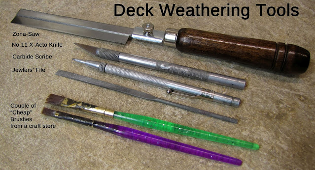
Deck Weathering and Distressing Tools


Tools:


X-Acto/Zona-Saw, carbide, file, paint brushes

The tools for the weathering are pretty basic.  Paper towels are needed as well, for keeping your work area clean and also used to adjust the weathering paint.

Paints: Apple Barrel:


A selection of Apple Barrel paints I like for weathering.

Black and Burnt Umber washes with Pewter Grey.
Then Pewter Grey, Khaki, & Territorial Beige drybrushing to bring out the details and highlights.

In Closing


Six flat cars with various deck weathering techniques together.

Hopefully, the video has shown some new techniques for how I do this weathering.  Maybe you'll try it on one of your flat cars as a incremental project?

Monday, May 10, 2021

Spring Switches on the SP - Tehachapi and Mojave Subs

 Following up to David Willoughby's excellent write-up on La Mesa Model Railroad Club's Spring Switch installations, let's have a quick look at where SP used spring switches on the Tehachapi Sub, mostly in CTC limits, and over the Mojave Sub, which was still Train Order-Timetable territory.

AT&SF 140 LAC, entering CTC at the end of Double Track at Bena.

The club installations of spring switches vary somewhat from the prototype due to several factors: the requirement to operate in several modes (TT/TO, CTC, ABS) for different eras or display running for the public.

Demo Video of Spring Switches in Operation


A clip starting at 8:00 of Jason demonstrating the operation of Bena's spring switch. - TSG Multimedia's Tehachapi Pass Tour video


Tehachapi Sub - Spring Switches, September 1955 ETT SI No.6


I have been looking through my Emplyoe Timetable Special Instructions No.6 from September 25, 1955, and pulled out the following bits of information on the use of spring switches.

    Rule 535. SPRING SWITCHES
    Spring switches not equipped with facing point locks are located as follows:
Location                                               Normal Position
Bena - West end siding                         Westward track
Caliente - West end westward siding    Eastward siding
Caliente - East end eastward siding      Westward siding
Bealville - West end westward siding   Eastward siding
Bealville - East end eastward siding     Westward siding
Marcel - West end westward siding      Eastward siding
Marcel - East end eastward siding        Westward siding
Tehachapi - West end No.2 Siding        Controlled Siding
Summit - East end siding                      Eastward track

Switch position indicator located at:
Bakersfield....Spring switch leading from back lead to inbound engine track.

Indicator does not indicate track occupancy.  When indicator displays red aspect, or is not lighted, careful examination of the switch must be made before passing over in eastward direction.

LMRC Notes:
The spring switches at the east end of Bena are installed for non-CTC operation on both the main and siding.  The main track switch is set for Westward track and the east siding switch is set for the westward main track.
During CTC operation, the springs switches function as regular switches, being reversed by the CTC Dispatcher and then the signals cleared.  After the CTC installation during the early years of WWII, 

West Bena's center siding's west main track switch was a spring switch, on the model we also have the inner switch at the west end set up as a spring switch allowing eastward trains taking the center siding to line the facing main track switch, then head into the siding without needing to line the inner switch.

The spring switches at Caliente have not been installed... yet.

The eastward siding at Bealville is not modeled, and the westward siding is combined with Allard, eliminating the need for any spring switches at Bealville as modeled.

The spring switches at Marcel need to be installed.

End of Double Track switch complex at Tehachapi with controls and track diagram. (Note switch to Nos.2 & 3 Sidings being rebuilt in this shot.)

The spring switches at Tehachapi as modeled include the pre-CTC spring switches at the west end on the main track and No.1 siding.  These two switches were made CTC controlled switches during the prototype's upgrades in 1943.  The end of double track switch on the main track in front of the depot is also a spring switch, allowing for movements onto the single track main west of the station.

Summit's east switch is also set up as a spring switch, which makes sense as it is entering a section of higher speed track, and the brakemen would have been busy cutting out the helpers at the wye near the west end of the siding for the last 20-30 minutes, getting air tests, etc.  Best to get the train moving again and down the hill to Mojave without leaving a tired brakeman 3 miles from Tehachapi or Monolith!

Bakersfield Engine Lead


Yard diagram showing the spring switch just above the word "Pullman"

This spring switch is set up on the "back track", with the normal position towards the inbound side of the engine house to direct eastward movements of engines into the inbound side of the engine house (obviously).  Westward engines coming off their trains, moving onto the back track can head down, spring through the switch next to the Pullman Shed, then back into the engine house without any manned throwing of any switches.  Making the fireman get down and line a switch in a yard where 'herders' are on duty would allow a time slip for the fireman to earn an extra day's pay for the violation!  Switching moves requiring an eastward movement on the back track must line the switch by hand for movement, then return the spring switch to normal operation.  This basically relieves the yard 'herders' from tending any of the light engine movements to "the house", especially this one commonly used switch which is 400-500ft out of the regular area where the herders and hostlers are working.

Mojave Sub - Spring Switches, September 1955 ETT SI No.6


    Rule 535. SPRING SWITCHES
    Spring switches not equipped with facing point locks are located as follows:
Location                                              Normal Position
Gloster - East end siding                     Main track
Ansel - West end siding                      Main track
Rosamond - West end siding              Main track
Lancaster - East end siding                 Main track
Lancaster - West end siding                Main track
Denis - East end siding                       Main track
Palmdale - East end siding                  Main track
Harold - West end siding                    Main track
Harold - East end siding                     Main track
Paris - West end siding                       Main track
Paris - East end siding                        Main track
Ravenna - West end siding                 Main track
Ravenna - East end siding                  Main track
Russ - West end siding                       Main track
Russ - East end siding                        Main track
Lang - West end siding                      Main track
Lang - East end siding                       Main track
Humphreys - West end siding            Main track
Humphreys - East end siding             Main track
Honby - West end siding                    Main track
Honby - East end siding                     Main track
Newhall - East end siding                  Main track
Sylmar - West end siding                   Main track
San Fernando - West end siding        Main track

Spring switches not equipped with facing point locks are located as follows:
Vincent - West end westward siding  Eastward siding
Vincent - East end eastward siding    Westward siding

Notes:


Mostly on the Mojave Sub we can see the example of basically every siding having at least one spring switch.  The end of the siding without the spring switch is usually going to be the end where the station is located and some stations had local operator controlled switch levers.  Saugus-Newhall is covered by Rule 605, Interlocking, which specifies the operations there in.

The heavy use of spring switches makes the rear brakeman's life so much easier, because he does not have to drop off, line the switch for the main, and then run after the caboose when the train is departing the siding.  When working on heavy grades, such as the climb from Palmdale to Vincent and down the Soledad Canyon to Newhall, especially at night.

In Closing


As far as the use of model spring switches go, they are nice to have in reverse loops, and other places which we want to have trains operate through and have regular routing selected, without needing the human operator to remember to throw the switch regularly at the right time.


Sunday, May 9, 2021

Spring Switches on Tehachapi Pass Exhibit - by DF Willoughby

 I've seen several comments around the internet recently asking about functional HO Scale spring switches.  LMRC club member David Willoughby was good enough to go dig up some photos and write the following document about the La Mesa Model Railroad Club's spring switch installations.

SPRING SWITCHES

on the

TEHACHAPI PASS EXHIBIT

by David Willoughby

Recently, I have received a couple of requests for information about the La Mesa Model Railroad Club's spring switches. First, I'll briefly describe our switch construction methods in general, and the linkage we use for regular switches between the motor and the points.

OUR SWITCHES ("TURNOUTS")


Center Siding Spring Switch at the East end of Bena. - D.F. Willoughby photo

Nearly all of our 750 or so switches (or "turnouts," as model railroaders and railroad civil engineers call them) are hand-laid on wooden ties. Our methods were developed over five decades ago, and were based on an article in Model Railroader around 1955 by author Robert F. Cushman. Initially, all frogs and points were made by hand from suitable nickel-silver rail; usually we now use cast frogs and points, some or all of which are available from Detail West.

One way our switches differ from many other model switches is that there are gaps between the frogs and closure rails so that the points and closure rails can be electrically connected to the adjacent stock rails. This makes the gap between the stock rail and the open point as close to scale as NMRA wheel standards will allow, without running the risk of a short circuit if the back of a wheel brushes against a the point. These days, this characteristic is sometimes called "DCC-friendly" because it minimizes the likelihood of a short circuit that can shut down a DCC booster, stopping every engine in the section it powers.

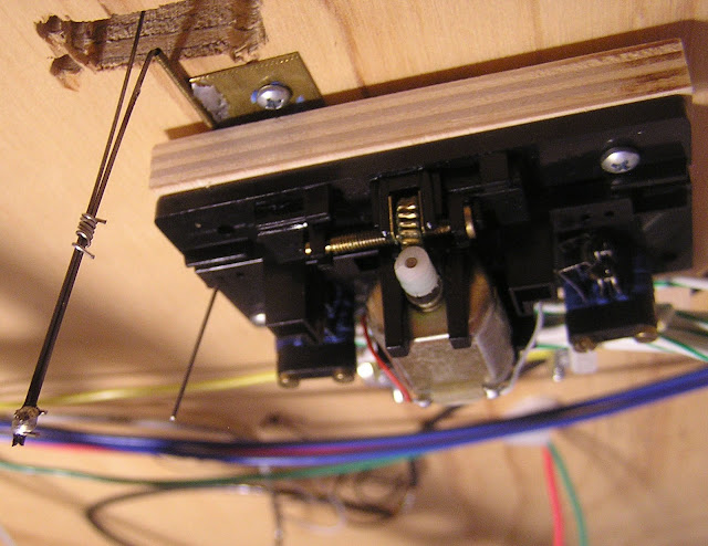
We use rail joiners on the ends of the closure rails loosely fitted to the heels of the points as a hinge, and connect them to an insulated throw bar using 00-90 screws, which are left loose enough that they don't bind. The throw bar, which is made of 1/16" thick phenolic, rides in the space between two adjacent ties. (These are usually the head-block ties, through SP standards specified the use of only one head-block tie for hand thrown switches.) In the center of the throw bar there is a hole for a piece of 0.030" dia. steel piano to link it to a switch motor. A hole through the ballast board and roadbed below the throw bar is widened into a slot to allow a wire from the motor linkage below the roadbed to move the points. The first photo attached shows what one of these switches looks; this one is a spring switch at the east end of the center siding at Bena.

"Normal" PFM Switch Motor installation. - D.F. Willoughby photo

Over 35 years ago, we standardized on PFM/Fulgurex switch motors, which were among the first motors available when twin-coil solenoid switch machines were still nearly universal in model railroading. (The PFM motors are no longer generally available in the U.S.) They have a plastic throw bar with holes at either end for a wire to link the points to the motor assembly, and cutoff contacts to stop the motor at the end of its travel. Our standard installation has the motor screwed to a small piece of 3/8" birch plywood with a couple of slots or oversize holes that slip over studs screwed into the bottom of the roadbed. We also put a Molex ® connector on the wires to the motor for motor power, and for the frog and auxiliary contacts. The connector and wing nuts on the studs allow a motor to be swapped out for repairs without any tools or soldering. The oversize holes allow the motor position to be fine-tuned so that the tension on the points is approximately equal in both positions.
To link the motor to the point throw bar, we fabricate a "Z-link assembly" using a piece of 1/32" I.D. brass tuning soldered to a small brass plate that is then screwed to the bottom of the roadbed. A piece of 0.030" steel piano wire is slipped through the tubing and bent upward at one end and downward at the other, forming a "Z." The lower end goes down into the throw bar in the motor and the upper end extends upward through the hole in the throw bar that connects the points. The second photo attached shows one of these standard installations.

SPRING SWITCHES


A clip starting at 8:00 of Jason demonstrating the operation of Bena's spring switch. - TSG Multimedia's Tehachapi Pass Tour video

The Southern Pacific used spring switches extensively, especially where they could be used in place of a power switch controlled remotely by an interlocking operator or CTC dispatcher. In timetable and train order territory, they were frequently used at the end of double track that operated by current-of-traffic, and on some single track sections in timetable-and-train-order territory, they were sometimes installed at the ends of sidings used for meets to eliminate the need for brakemen to throw a switch to leave a siding and then line it back after clearing the points. We have also installed them in places where have return loops ("balloon tracks") that we use when operating our model railroad for the public. That way, operators can send a train down the mainline into a loop some distance away without having to be close to the loop watch the train and throw the loop switch while the train is in the loop. This is particularly useful when a single operator is running two trains.

East Bena, center siding spring switch. - D.F. Willoughby photo.

For our spring switches, club member Kent Thaeler modified our switch motor linkage arrangement slightly. Instead of making a Z-link, the 0.030" wire inserted into the brass tube is bent downward on both ends to form a "U-link." A piece of 0.024" phosphor-bronze spring wire is then inserted through the hole in the throw bar between the points, with a short bend at the top to keep it from falling through the hole. If the throw bar rubs the sides of the slot it rides in, this can cause too much friction for the light spring tension to overcome, so it's important to be sure the spring wire doesn't pull the points away from the closure rail. A piece of wire (bus wire?) is then coiled around the U-link and the phosphor-bronze spring wire to bind them together, and can be slid up and down to fine-tune the spring tension on the points. By adjusting the position of the coiled wire and the position of the motor on the studs, the tension can be set so that there is just enough tension on the points to move them solidly against each stock rail, but not enough to derail a short freight car weighted according to Club Weight Standards (modified NMRA Recommended Practice).  (Edit by Jason Hill, see LMRC club car standards in my post on Ratings & Operations.  Some cars as light as 2.5 ounces regularly operate through spring switches, when properly adjusted.)

Spring switch motor installation at Tehachapi. - D.F. Willoughby photo

I've attached two photos showing these linkages at two different locations. There is one minor difference between these two installations. For the earlier one, the coil of wire for adjusting the tension is soldered in place. This makes later adjustments rather difficult. On the second one, the adjustment coil is still movable, but the ends of the U-link and the phosphor-bronze spring have been soldered together, with a large enough blob of solder at the bottom to keep the ends parallel and keep the coiled piece of wire from falling off. Once the spring wire and the U-link are soldered together, there's no need for the bend in the wire to keep the spring wire from falling through the throw bar between the points, and the only way to remove the throw bar is to loosen the switch motor and unscrew the U-link from the roadbed to make it possible to drop the linkage assembly.

The frog sections of most of our switches are less than about two inches long, with gaps at both ends. We generally leave the frogs of our spring switches unpowered. Large steam engines, and diesels that pick up from both rails on all axles have no problem with them at all. Only the smallest steam engines and tenders lose power briefly when passing over the longer No. 9 frogs. If this is a concern, an electronic frog circuit such as Tam Valley's Frog Juicer can be used to power the frog.

There are occasional derailments when there is not enough downward force on a wheelset trailing through a spring switch to push the closed point out of the way. Our car standards specify minimal slack in bolster screws and most of our freight cars use rigid frame trucks and lifting one wheel off the rail wheel lifts the whole truck frame and starts to tilt the car. Cars with loose trucks that are loosely sprung or fully equalized may derail more easily on spring switches, as it takes less force to lift an axle off the rail trying to push a closed point over. Pilot trucks on steam locomotives sometimes require increased downward spring tension, or a small weight glued onto them, to provide enough downward pressure. Two-wheeled pilot trucks seem to be particularly prone to this kind of derailment.

Spring switches can be a bit of a maintenance headache. Problems arise when dirt, dust, ballast or other residue collects under and around the point throw bar. This increases its resistance to movement so that the gentle pressure applied by the phosphor-bronze spring wire is no longer sufficient to reliably seat the point against the stock rail. This residue can often by dislodged by moving the points back and forth vigorously with a finger. If that doesn't work, try removing it with a pick, or by blowing it out using a straw or an aerosol can of air. If the contamination is under the throw bar, it may be necessary to remove the points and the throw bar to clean it out. Tight clearance around the throw bar will make it particularly likely to be sensitive to contamination, and can only be fixed by removing the the points, and the throw bar and carving out more clearance with a knife or motor tool.

So far, we have installed about ten spring switches on the Tehachapi Pass exhibit. Several are used in places that only see service during formal operating sessions that take place about a half-dozen times each year. But the ones on the reverse loops are used daily when the railroad is operated for the public and trains have to go through them at each end of every trip over the mainline. Their convenience far outweighs the disadvantage of their occasional need for maintenance.

In Closing


Thanks to David Willoughby for writing up what the club has done to make our spring switches work.  Most of my experience with the pilot or trailing wheels derailing are usually caused with the leading wheelset trailing through the switch, and trying to actuate the points to move with very little lever moment.  However, a properly adjusted spring switch should be able to handle the club's minimum weighted cars (spine intermodal cars and cars with very high CG counts, such as Athearn 65ft Mill Gondolas, only weighing around 2.5 ounces.)  It's pretty interesting to watch a train going over the spring switches and hearing the points snap back to "normal" route under middle of each car going by.

Jason Hill

Thursday, May 6, 2021

SP Jawbone Branch (Part 26) - Engine Spot & Water Track Detailing

Currently, layout construction progress has slowed slightly, but I've been working on researching some other details on the wye.  

Owenyo transfer decks with coaches looking north, circa 1940. - owensvalleyhistory,com - ebay35_owenyo_sml

The Owenyo Local would lay over at Owenyo for the day while the crew rested across the NG in the 'boxcar' hotel, visible beyond the Owenyo station's TO boards.  The mixed train's RPO and coach are resting at left, in the siding.

Owenyo Engine Spot - Cropped from high angle shot from transfer dock pole around 1940 - owensvalleyhistory,com - owenyo dennis burke_sml_r

Zooming in on the above photo shows more carbodies inside the wye, and fairly under exposed oil tanks, a profile of the oil pump house and an under exposed 2-8-0 simmering away "on-spot".  The passenger carbody appears to be either SPNG 7 or 8, a combine with two windows on the short end of the car.  SPNG No.7 became No.17 before she was retired, but it looks like this probably was her final resting place inside the Owenyo Wye.  I may see if I have the space for this little cluster of carbodies around the flagpole.

Engine Spot


A basic boiler watchman would be set or the fire would be cut and hold pressure until the crews went back on duty.  Most photos taken during the day time when the engines aren't switching, show the engine spotted next to the oil tank on the eastern curved section of the wye. 

Owenyo engine spot with SP 2758, oddly with Train 792, I'm not sure the year this could be. - Eddie Sims collection

Notice in the photo, that there appears to be metal plates under the firebox area of the engine.  There was a story in SP Trainline of a new-ish fireman trying to get two 2900-class 4-8-0s refired on an Oregon branchline after the engine watchman wandered off overnight, allowing the engines to go cold by morning.  His inexperience lead him to over fuel the relight of one of the engines... causing oil to spill onto the ground and when the firebox caught the light from his fuzee, the fire spread down onto the ties, into the previously spilled oil and ended up gutting the engine!  The metal under the firebox area here is probably to help prevent damage to the track in case of a fire "dropping" in the firebox down to the track.

The dark dirt/ballast under the front of the engine and leading tender wheel probably from the daily lubrication of the engine before going back to Mojave.  The white area around the 4th driver is probably blow-down scale deposits from the water/mud in the boilers.  Also notice that the ties are rather exposed from the 2nd driver back under the metal plating.  I'm not sure if this is from years of boiler blowdowns right there, or if there is another reason that the dirt/ballast has been left out of this area.  Still it is an interesting thing to model, which I intend to do.

More detail of the engine spot, with spacing for a 2-8-0 to be spotted.

The compression factors on the curved areas of the wye will mean that I can't really have all the space that the prototype photo shows... I'm going to model the features in the photo, mapped out to the size of a C-class 2-8-0, and positioned so that the big 3266 and Mk-2/4s can fit between the small dirt road and as far from the fouling point of the siding as possible.

SPNG 8 Owenyo with oil tanks - Mark Van Klaveren - owensvalleyhistory.com - mark_van_klaveren03_sml

This photo shows some lighter color weathering on the SG oil tank.  There's also some smaller pipe connections on both sides of the 'engine spot'.  I'm not exactly sure what those would be for.  It seems strange that they are back behind the tender, based on where the engines are usually spotted.  Perhaps compressed air.  I don't know why they'd have engine washing stands there.  Perhaps they were compressed air connections to apply forced lubrication into the rods for the return trip.

I guess I also need to figure out where the various power poles need to be mounted, which will make switching some of the areas and navigating my hands into joints a challenge.

Tail Track and Derails?


Of note here is that there doesn't appear to be any derails on the engine spot, where the local engine layed over.  A derail is required on the SP at both ends of any track where an engine is to be left.  Perhaps the SP figured that the placement of the engine spot at Owenyo was different because an engine rolling away would push through the switches at the east end of town and stop against the tank car fuel ramp, and if it rolled towards the tail of the wye, then the tender would go off the end first.

Completed wye tail flex track and wye switch roughed in.

If the wye tail track failed at Owenyo, the engine better be able to pull itself out of the problem.  The nearest relief engine was at Mojave, 143 miles away!  So better to put the tender out on the 'bad track' than the engine.

East Wye Tail


Owenyo SG-NG transfer ramp foreground & "NG Pit" and SG ramp in the background. - Rich McCutchan  - owensvalleyhistory - slim rails63_sml

The east tail of the wye also doubled as the tank car transfer and extended up onto an elevated track, so I doubt that track was "bad", plus there was room for the engine to move out onto that tail farther there.

East wye tail shimmed up with extra tie.

I've been considering showing the start of the ramp to the 'fuel ramp' along side the NG's 'fuel pit' track at the north end (seen in the back of the model photo above).  The main challenge here is that the prototype had, I believe at least one engine length before it started to ramp up.  My model's been compressed a bit more.  The NG track's already dropping down into the bit.  The main concern here is not making too fast of a vertical curve which would cause problems with the pilots of the steam engines planned to be used on the branch.

Water Tank & Track


SP Water cars at Owenyo - Sept 19, 1950 - Chard Walker photo - Mike Massee collection (cropped)

Just east of the road grade crossing to the station, two water cars are spotted in front of the water pump house.  This photo is about four years before the black water tank was moved to Owenyo.

SP Water Tank & Loading Docks - much thanks to Alden Armstrong for permission to use these shots!

In 1954 the water tank at Diaz was removed from the Employe Timetable (ETT).  At the same time a engine service water tank is added to the ETT at Owenyo.

Owenyo SG water Tank - after SG was being razed 1960 - Alden Armstrong

The standard gauge was being torn up back to Lone Pine, but the water tank still stands for a few a little longer.

I'll be looking into contacting the CSRM again about getting the Val Maps for Owenyo, Bartlett and Little Lake this week, so maybe I'll be able to get more information on the size of the structures around Owenyo.

In Closing


I'm hoping to start construction of west Owenyo in the next week or so.  Also the 00-90 screws I need for the switch point bars should be showing up soon, so I can return to working on the track switches.  I've picked up a bit more 14 AWG wire to make the bus wires.  I still need to pick up some plugs to join the track power and lighting strips under Owenyo, between the modules.  Several things to keep working on.

Jason Hill

Related Articles:


SP "Jawbone" Branch Index Page - Links to all my blog posts on my new Jawbone Branch layout.

Saturday, May 1, 2021

New Drawbar Mount for Athearn-Genesis 120-C-6 Tender

In this quick blog I'll be looking into the process of converting Athearn-Genesis 120-C-6 tender for use with standard brass steam engines.

Balboa Models, SP 3266 mocked-up with Athearn-Genesis 120-C-6 class tender.

The Prototype


A quick side note on this prototype, the 3266 was the only Mk-5/6 rated to Owenyo on the Jawbone Branch, which makes it very unique.  Usually 3-4 Mk-2/4s were rated at any point from 1950-1954 specifically by number for operations.  The Mk-5/6s from Balboa are quite common brass models to be had over the last 10+ years.  So this is a fairly easy prototype engine model to make.

SP 3266 near Olancha with excursion to Owenyo in 1952 - Phil Serpico photo - owensvalleyhistory.com - southern_pacific012_t

I don't want to go too far down the prototype rabbit hole here, but the SP 3266 was used in the 1952 fan excursion trip run to Owenyo with the 3237.  It seems from a couple of the photos, such as the one above, the SP 3237 was only needed for the eastward (north compass) trip to Owenyo.  The 3237, may have departed and returned to Mojave, while the 3266 remained in Owenyo with the fan special for two more days.

The 3266 probably was a regular Mojave based engine during that time, normally working the KI (Tehachapi) local and the "Blitz" (Palmdale) local.

The Problem


The SP 3266 Balboa model came with a standard (but incorrect) 100-C-1/2 tender.

Balboa 100-C-1/2 class tender with weird UP-style high-speed trucks.

As far as I can tell the SP swapped all of these smaller tenders to other smaller types of engines.  The SP 3266 during the post-war years was upgraded to 120-C-3/6 class tender, along with most of her sisters also receiving 120-C-series tenders.

However, the brass 120-C-3/6 class tenders are hard to come by... and when they're found, they often command similar prices to that as the Mk-5/6 engine itself!

SP 3266 laying on her side - showing the problem with the tender.

The Solution


Athearn-Genesis unlettered 120-C-6 Tender.

Athearn-Genesis came out with the 120-C-6 tender with their 4-8-2 MT-4 class engines.  They were also made available separately both painted and lettered and undecorated, but painted.

The Catch


The Athearn-Genesis model has a unique drawbar arrangement.

Unfortunately, the Athearn-Genesis model comes with a rather goofy drawbar design... a similar concept to the BLI's articulated cars, which has an open 'claw' on the engine, which snaps around a post inside of the tender, above the frame.  I don't trust this design to handle heavy draft loads, plus the brass engines are equipped with a standard metal drawbar with two holes on the tender side to fit around a pin or screw.

Time to Disassemble!


Due to the large number of plastic parts around the upper shell of the tender, and the front deck plate is fairly fragile plastic, I needed to disassemble the tender with two screws.  One screw is in the middle next to the brake cylinders and one between the rear two axles of the rear truck.

Interior of the SP 120-C-6 class tender.

The interior of the Athearn-Genesis tender is... interesting.  The brass-style drawbar will make things a little tight to have a larger group of wires running between the engine and the tender under the frame.  I'll only be wanting two pairs of wires going to the engine where the decoder is to be located.  Each side of the tender wheels pick up power, and the two wires to the rear headlight on the tender.

New hole drilled with No.50 drill bit, tap for 2-56 screw.

I used a power drill motor with the No.50 drill bit pressing against the tender frame, which I was holding against a piece of 3/4" plywood.  The plywood was needed to keep the fine details, such as the vertical grab bars and ladders at the tender's rear.  A 2-56 tap is then used to cut the threads in the new drawbar hole.

I'll be removing the jumper connection between the engine and the tender.  This requires removing the screws at the front of the large weight stack, and lifting the weights off for now.  The front screw in the PC board is removed and the PC board is lifted up.  Allowing the wire jumper to be unplugged and removed.

Tapped 2-56 hole ready for 3/8" x 2-56 screw.

The 120-C-6 tender is reassembled, ready for 3/8" x 2-56 screw.  I cleared the forward drawbar hole with a No.42 drill bit (clearance drill for 2-56 screw).

SP 3266 with new drawbar screw in place.

In Closing


SP 3266 with completed tender drawbar conversion.

This is not the last time I'll be going into the tender to rewire it and probably adjust the weight balance over the front truck.  The DCC sound decoder in this engine will be in the lower front of the boiler, between the smokebox and the forward of the gear box.  The speaker will be in the smokebox.  This is my preferred method of installing DCC decoders in steam engines, as it keeps the majority of the wiring in the engine and the runs very short.

I'm planning to do a blog post specifically on the DCC installations in brass steam engines, so this post will be kept to just what is unique about the Athearn-Genesis 120-C-6 class tenders.

Jason Hill

Related Articles: