Showing posts with label Painting. Show all posts

Tuesday, October 18, 2016

SP 2701 (Part 2), 60-CC-1 from a Model Power Coach

Well, some progress has been made on the SP 2701 since Part 1 of the build.  I will also mention that I've done some improvements to my SP HW Passenger Car Index page with new example photos and a few new car classes represented now.

Interior & Walls

Leading this update is the construction, painting, and installation of the chairs and some partitions around the toilets, and painting of the interior.

Interior added to SP 2701 - Note the dark green window shades.

I should first mention that I used dark green manila filing folder material for the dark green window shades on this model.  Some SP coaches, All-Day-Lunches, and News Agent cars had this.  Best to look at photos to see which cars had it, and which had a light tan shade.

Similar strips of PSC seats prepared for SP 1005.

The seats are Prescision Scale Co. 33312.1 (Chair Car) seats, they are injection molded in pairs with small legs on them.  I started with the uncolored gray seats, and painted the floor strip of .400" x 0.020" strip styrene a nice shade of "Seafoam" green from StarBrand, which is actually a pretty good match for the interior color used on Athearn's Streamlined 77-C-3 chair cars.

I then masked the floor and painted the seats with a mix of Freight Car Red (FCR) also StarBrand.  This again was a pretty close match for the colors used on the MTH and Athearn Genesis Daylight chair cars.

The seats were glued to the styrene strip 0.460" apart.  At the front end of the car there will be a set of seats looking back, however I did not install those at this time.  The lighting bar-strip was not glued in and I removed it for this part.  Checking the drawings I glued the seating strips in to get a good location compared to the windows of where they line up.  This is really a matter of choice, as the Model Power is missing one large window.  So in the middle of the car you can either let the seats not line up with the windows and have the right number of seats, or you can have the wrong number of seats, but line up with the windows.  I chose to have the right number of seats, and oh well about the windows.  I might have decided to go the other route in hindsight... but it's too late now! - (More on my thoughts of changing models after the fact).  At this point it's not reached a high enough mark on the "Really Annoying" Meter to worry about.

Photo from before the interior was installed - Notice the major hole... WATCH YOUR STEP!

Styrene sheet was added down the middle of the car as well to cover the major holes that were left in the Model Power body tooling.  This will help hide the holes as seen in the photo below.

SP 2701 with interior mounted and partitions around the ends of the seating area.

The partitions are 0.02" sheet styrene cut 36" wide and even with the top of the carside.  Notches are cut in the edge nearest the carside for the roof flange to clear.  Extra scrap squares of sheet styrene are glued over the "end windows" in the car interior.  I am not sure why both MDC and Model Power (copied) have these end windows into the toilets... Not kosher for 1910 certainly!  Probably they did one set of tooling for the end windows in the end wall of the observation car and put them in all their models as a general endsill wall.

The left end window (bottom left in the photo above) is also is covered with non-"Magic" Scotch Tape, which causes the "fogged" look, usually associated with the toilet windows on coaches and chair cars not fitted with expensive "etched" glass or prismed windows.  This can also be seen below.

Another view of the interior, also we can see a bit of the roof with the vents painted.

The soldering tabs can be seen above at the end of the LED strip.  The wires from the trucks and markers will attach there.

I'll end this update with a photo of the car showing what the car looks like without installed marker lights.

Non-marker end of the SP 2701

In some ways installing the markers after the HiTech Diaphragms are installed is more of a pain, but on this model it will need to be done.

That does it for now for Part 2 of the SP 2701 build.  In Part 3 I'll be showing the installed OwlMtModels marker kit and finishing the underbody frame and installing assorted detail parts.

Jason Hill

Monday, September 12, 2016

SP 60-C-5s, (Part 1) SP 1005

In this series of posts, I'm working on some Soho 60-C-5 coaches.  The first two are both the same class, yet quite different cars as examples of what happened to SP and T&NO's large fleet of 60 foot coaches over the years.  Both the SP 1005 and the T&NO 777 are based on the Soho model of a 60-C-10.

SP 1005, 60-C-5 Chair

SP 1005 with window shades and replaced roof vents.

SP 1005 started life as Northwestern Pacific (NWP) 401 and was fitted as a "smoker" coach with a partition mid-car.  The NWP 401 spend her early carrier working north of San Fransisco Bay until 1935, when it was transferred to the SP and renumbered 1005.  Like all 60-C-5s it was built with transom windows of colored glass and end windows.

Here's the SP 1005, before I changed the roof vents.  The end-window can be made out in this photo as well.

In 1940, the SP was short of cabooses, so SP 1005 was reassigned and numbered into the caboose series as SP 998.  Mid-war it was decided that the SP needed more coaches to deal with the crush of the troop movements and was short passenger capacity.  SP regained her status as a revenue passenger car in 1943 by having 60-seats worth of second hand chair seats installed.  Only a handful of the SP 60ft coaches were equipped as chair cars instead of coaches, but didn't go all the way and get air conditioning.

SP 1005 lasted through the war and was one of the few cars that still retained its gas lighting in 1945.  I've not really tracked down any more data on the 1005 as it kicked around between various unknown assignments until it was photographed in Oakland in 1947 by E.R. Mohr, Pg 120 in SP Passenger Cars Vol1., by the SPH&TS.  The green glass of the transom windows were still intact in the photo, by 1950 most SP coaches and chair cars had these plated over.  The last being covered in 1952.  This was mostly because of problems with leaking in the transom windows.  The 1947 photo was only 6 months to a year after the SP changed to "Southern Pacific" lettering above the windows, so it's very understandable that this car wasn't a priority to repaint.

In 1952, the SP 1005 was retired.  A year later, it was reactivated as a caboose for the second time as SP 953.  Another car had taken over the Caboose SP 998 number.  By 1954 the 953 was retired again and what happened after that is unknown, it was probably scrapped at that point.

Modeling the SP 1005

Here's a Soho 60-C Coach in similar starting point to where the SP 1005 started

I started this project with a Soho 60-C-10 with transom windows.  My problem is by 1948-1952, when I model most of my equipment, these transom windows were becoming VERY rare.  I chose the 1005 because of it's somewhat unique history.  It would also fit well into my Tehachapi Mail (Nos.55/56) consist to mix up the regular 60-C-coaches, or in other mixed assignments typical of the "wandering" SP non-A/C coach after WW2.

Soho SP 1005, 60-C-5 in-process - Note the green glass in the transom windows.
I'm modeling the SP 1005 after its 1943 conversion to a 60-seat Chair Car, this means I do have to make some modifications to the "early" Soho Coach.  The car is painted Dark Olive Green and my standard mix of off-black gray for the roof and underframe.  "SOUTHERN PACIFIC LINES" decals are used on the car to show another car that hasn't been repainted since 1946.  Also, remember this car is pretty clearly not in the best condition.  It's been retired once already, and but for the needs of WW2, it would have stayed as a caboose.

Here's a photo to show off the Tamiya Clear Green painted glass transom windows

Windows were installed using clear sheets of styrene.  I masked off everything except the top 18" of the windows.  This leaves what will be the transom windows exposed.  I used Tamiya Clear Green to tint the upper glass a lovely green color.  Be sure to tint the inside of the windows!  This will help prevent scratches to the tint and also keep the mounting glue from de-bonding the tint as well.  Once dry, I installed the window sets with Testors Canopy Cement.  Be extremely careful to have the green glass and clear glass change fall behind the narrow header of the main windows.

The diaphragms are again from HiTech.

Underframe

Basic Underframe

John Ruehle made me a new underframe for the car.  John used a piece of 0.040" sheet for the main floor.  Then C-channel 0.185"x 0.150" was used for the main centersill.  Crossbeams of .070"x 0.050" I-beam were glued on to represent the floor supports.  This underframe doesn't have any of the diagonal bracing that the 69-BP-30 (SP 5199) or the rest of the SC&F kits have.

John mounted passenger brake "UC" type gear on the bottom of the car.

Electrical Generator was already fitted to the underframe

Looking at the SP 1005, with its "rare" gas lighting by 1947, certainly rare by 1952, I will be adding the gas tanks.  However, I will probably add a battery box, because I'll be adding the OwlMtModels 10002 Gyralite Marker Light.

Styrene shims added to bolster of Walthers 920-2124 on SP 1005.

I shimmed the bolsters and installed a sheet of 0.02" styrene across the top bolster of the Walthers 8ft Pullman 4-wheel trucks to result in the right coupler height.  I plan to fit the car (in Part 2) with my standard LED lighting strip and OwlMtModels Pyle Gyralite marker and tailgate kit for end-of-train service.

Window Shades

Completed window shades installed in the SP 1005

Window shades for the 1005 are made from manila card stock file folders.  One folder will do about 30-50 sets of window shades.  I don't use normal 3-5lb paper because, unless painted, it is too translucent for use with the LED lighting installed, even at lower settings.

Cut a strip of card stock a scale 24"x 50'6" and make pencil markers where the window columns are across the full shade.  I then mark where I want the window shades to be cut off at.  This will be on average, make the shade 12" high, however I like to make somewhat random cross cuts with a Xacto to show passengers using the shades and moving them to where they want to be.  These horizontal cuts are then connected with small vertical cuts to make a prepared window shade.

Abbreviated shades to keep the green transom windows clear. Tamiya tape used to mount the shades.

Remember that cars freshly out of the coach yard should have all their shades nicely trimmed 1-3" below the top edge of the window, or whatever the railroad considered "standard dress" starting position.  A car ending its trip will be all over the map, some shades high, some low, some in the middle, some unused if the seats were empty the whole trip.

Once trimmed to length (This time I was also making standard longer ones for my SP 1050's window shades) I used 1/16" wide by about 1/4-3/8" long strips of Tamiya Masking Tape to hold the shades in place.  The tinting on the windows was actually thick enough, once the mask was removed to make a nice stopping ledge for the shade material to catch on.  The tape was then applied with the end of a knife blade vertically where the window columns are.

Bathroom window covered with Scotch Tape

The toilet annexes will have etched glass or prism glass, I use standard Scotch Tape (not the magic clear stuff), so that when I apply it to the clear plastic windows it will remain foggy.

"Globe" Roof Vents

Here's the 1005 with new MDC "Globe" vents

I removed the Soho stock Utility Vents over the main seating area.  I still need to remove the vents over the car ends.  There was a slight mishap and I scratched the roof paint pretty badly there in the center of the car.  When I do the additional end vents I'll touch up any other scratches.  The square holes left from the old vents were roughly in the right place on the roof, so I used my ~0.085" drill bit in a pin vise.  As always drilling through brass sheet, be careful when 'breaking through' with the tip as the drill will tend to catch.

The MDC vent pieces were easily glued into the holes with ACC.  Make sure not to put the car floor back on for a day or so after gluing.  This will allow the glue to "gas-off" and not fog the windows.

Interior

Here's the SP 1005 with the seating strips of PSC 33312.2 Chair Seats

Because the SP 1005 was pulled back into service as a chair car, she lost her original 72-seat coach configuration.  Instead a 60-seat chair plan was used, probably from second hand chairs from other 60-CC-1s upgraded in 1941-42.  Trying to find exactly the right seats is a bit challenging.  For this car I'm using Precision Scale Co. #33312.2 chair seats were used and mounted to a strip of 0.03"x 0.188" strip styrene was used to space the seat pairs apart.  The inside of the car sides have flanges, which add strength, however they do make the installation of interiors a bit tricky.  Once glued up, these strips of seats will be able to be easily mounted to the inner ledge of the car side.


The 15 rows of seats are evenly spaced every 3.28 ft over the 50'4" length of windows.  In laying this out I come to find out that the car is about 2 feet too short, all in the toilet windows section of the car.  That doesn't really effect the modeling of the interior though, just interesting to note.  The last pair of seats are showing in the floor plan reversed.  These would have been the walk-over type seats, possibly from the A/C'd 60-CC-1s, which new seats in 1942.  SP had a way of reusing second hand seats on older cars.

The center isle will be purposely left open for access to the lighting strip in the roof.

LED Lighting

An example of a car I installed this type of lighting in

I don't plan to mount the interior seats strips until I have the LED strip installed and lead wires for the trucks and marker light are installed.  As a sneak peek, here's the light strips that I make myself.  I use 0.100" x 0.250" styrene strips as a backing support for the LED light strip.  The leads are easily soldered onto the ends of each 3" section of LED strip.

LED lighting components

In the center of the LED coil, is a 3" strip for the SP 5199 project I'm working on, and above that are two 6" strips for the 60 and 70 foot coaches I'm working on at the same time.

Beauty shot in closing here

That does it for this part of the SP 1005 Build.  In SP 60-C-5s, Part 2 T&NO 777 I cover building a car without the green transom glass windows and more detail of the underframe construction.  Please follow to be notified when I post the next blog update!

Jason Hill

Related Links:
Of some interest is Sunset Import's new announcement of plastic 60-C-5s coming to HO, follow this link to my blog post with my thoughts on it. GoldenGateModels Harriman Cars in HO

Or you can follow this link to my blog on building the SP 2701, a 60-CC-1 (Part 1) from a Model Power Coach

Friday, September 2, 2016

Modeling SP 2701, a 60-CC-1, from a Model Power coach (Part 1)

Model Power many years ago produced a "Harriman" 67ft Coach with arch-roof.  These cars are still a good stand-in for several classes of cars.  I'll be covering the options of how to use the MP Coach as a stand-in for both the SP's 60-CC-1 Chairs and 60-C-3/4 Coach class cars.
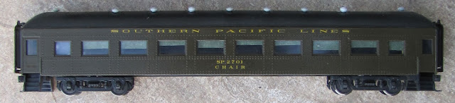
SP 2701, 60-CC-1, modeled as it appeared in Oakland during March 1953 with a stand-in Model Power 67ft coach.

The cars were 60 feet long over the "Endsills" which were the inside of the doors.  The vestibules, doors, steps, and end sheets of the cars were never counted in SP and UP Common Standard Designs. Only the usable floor space inside the car was counted and used for the Common Standard class.  This is why the Model Power car shows a length of 67 feet, is they're counting the length to the end-sheets of the model, over the doors.

Here's a cheap Ebay grab for more MDC kitbashing fodder!  I usually cut them up for other projects.

Model Die Casting (MDC/Athearn) 60 foot coaches are not correct in that they're measuring over the 60ft body length, not frame length, so these models are 7 feet too short!


Prototype Car History


SP's first two 60ft steel coaches, SP 1806 and SP 1845 were built in July 1906 and July 1909 and assigned to class 60-C-1 and 60-C-2 respectfully.  These cars continued the SP's wooden coach design of a single 29.25" window at the "West" end of the car, then eight 4'3.5" windows in the middle of the car, followed by two 29.25" windows on the "East" end of the car.


SP 2810, ex-1806, the first steel passenger car on the SP.  Also the only 60-C-1, became 2810 in 1953 for express service.

The next two classes of Common Standard coaches (60-C-3 and 60-C-4) were built to the same standards as the 60-C-2.  These car orders totalled 219 cars for the Pacific Lines and 35 (60-C-4) for the Texas Lines.

SP 2310, an example of the later 60-C-5 through -10 class cars.

Following 60-C-series Coaches for the SP were of paired window design and will be covered later.

The 60-CC-1 Chair Cars were built in 5 lots of cars starting in 1909 for the IC and UP.  The SP's 52 cars were in the fourth lot, Lot 3840, delivered between November 1911 and April 1912.  These were in two number series on the SP roster.  SP 2500-2530 (31-cars) and CP 2700-2720 (21-cars).

The 60-CC-1s had 9 large windows with 12.25" columns between them and only single smaller windows at the ends of the car.  SP's following classes of 60-CC's were of paired-window style construction, not the picture-window style of the 60-CC-1s, and will not be covered here.

Model Power 67ft Coach part way through rebuilding as a 'stand-in' 60-CC-1 as SP 2701.

The MP car is actually a couple of feet longer than the KenKidder (SP 2810) or Soho (SP 2310) cars shown above.  This is one reason I try to number my odd-ball "stand-in" cars as other than 'general service' cars where you'd be seeing them next to more correct models.  I'll cover modeling the SP 2810, ex-1806, in another post in more detail.


Getting Started


The main issue with both the MP and MDC models is that the manufactures basically mixed the dimensions of the windows and columns between the 60-C and 60-CC class cars.  This results in the MP car having no room for the second single window at the East end of the car if it was to be a 60-C-3/4 and only 8 large windows if it was to be a 60-CC-1.

Because the look of the car appears to be more of a 60-CC-1 without the second East end window, I've elected to number my stand-in model as one of these, ignoring the missing 9th large window.

Starting with the Model Power car out of the box, I disassemble the whole car into its basic parts.  A very long screw-boss extends from the center roof of the car through the interior, weight, and underframe to hold the car together.  It also is visible in the interior of the car, through the windows.  I don't care for this 'feature' at all.  So one of the first things I do is cut that out.  This leaves a hole in the center of the floor.  There are also several other holes in the floor, just inboard of where the trucks bolsters will mount.  Again, I'm not too worried about those at this time.  Later interior and underframe construction will cover those.

The window glass comes out and the trucks pop out of the rudimentary underframe, leaving the body and roof.  Model power cars are what I consider a "budget" model.  These should be able to be found on Ebay for maybe $10 at a good price.  Swapmeets are the other good place to get them.  Perhaps estate sales at your local hobby shop.

Painting


Once the car is stripped down to basic components, I tried to strip the "US ARMY" lettering off the model, this has some success, but I was also trying to avoid getting into the poor quality plastic carbody.  Old Rivarossi HW cars, such as their 12-1s and ATSF Diners and Cafe-Observations have this problem too.  The old Model Power paint hopefully will help protect it somewhat from the lacquer StarBrand Dark Olive paint.

I painted the body pretty early in the rebuilding as there wasn't a lot to change on the body.  I decided on this stand-in model not to replace the grab irons.  The steps would be black, so I left those off until painting of the body was done.  The roof as well would have the vents repositioned and then painted off-black, so those would wait as well.

The body was painted StarBrand SP Dark Olive and then gloss coated for decalling.  I chose to model SP 2701 as an interesting car to model because of it keeping the "SOUTHERN PACIFIC LINES" lettering into the 1950s.  See page 58 of SP Passenger Cars Vol1., published by the SPH&TS, for a nice view of the SP 2701 in Oakland on March 16, 1952 by W.C. Whittaker.

The SP 2701 is also interesting in that it didn't get air-conditioning, and kept the lettering as "CHAIR" under the reporting marks into the 1952 photo.  Most SP Chair cars were upgraded to "Deluxe Chair" during the period between 1936 and 1941 for service on premier and higher rated secondary trains like the Owl and West Coast.  The seating in the 2701 still looks like it has the nicer seating with head-rests, so it would appear that the SP 2701 is still internally a non-A/C'd chair car.  Also it did not warrant get repainted after the June 1946 change in lettering until at least March 1952.

I plan to use this car in various assignments, anything from a rider car on a special Pullman movement to a rider on an SP Mail & Express train.  It could even show up on a regular mail train (Nos.55/56, the old "Tehachapi" Mail for example) in place of a standard non-A/C coach.  The non-A/C'd chair cars were defiantly in a weird place in terms of assignments after WW2.  I could also see them being assigned other 3rd rate passenger trains and locals, such as the Rogue River, Shasta, Suntan Specials, and other short haul trains that wouldn't rate getting nicer A/C'd coaches or chair cars.

Mechanical Changes


The partly rebuilt underbody showing the basic mechanical changes.  (Left to Right: weight, bolster & frame, steps)


I started with the mechanical changes to the car.  Once painted, I glued in the end steps from a cut up MDC coach.  These were cut off about 18" inside the endsill of the car, so it would 'key' into the sides of the car for a good joint.  ACC-gap filling glue was used for this, as the plastic wasn't a tight friction fit.  The joint at the endsheets to the end of the underframe sections was also glued at this time.  The floor of the car is pretty high, as the original Model Power underframe encased a steel weight above it.  I scrapped the steel weight.

After weighing the parts of the car with the Walthers (920-2124 - think that's the current number) Pullman 8ft 4-wheel trucks that will be used, I get a rough idea of how much the model will need to weigh.  I use the La Mesa Model Railroad - Car Weight Standards chart for this.  - "A 70ft car of non-metal construction should weigh 6.25 oz. if it rolls on a 1.5% grade."  Checking against the weight for the same car if metal construction shows it could be as high as 8 or 9oz.

This is worth checking because as a passenger car, it might be run with other 'heavy' brass cars.  The lighter car should be ok, however with diaphragms the cars are actually in sprung, physical contact with eachother.  Plastic cars in those situations I've found need to weigh a bit more than the standard "Non-Metal" car weight.  The 1.5% grade figure is pretty easy to get with the Walthers trucks and being sure to lightly dress the bearings with an axle reamer.

A new sheet lead weight is cut to bring the car up to a weight of 6.9 oz without the interior parts or underbody detailing.  This weight is 1/8" sheet lead, 1.3" wide (just fitting between the lower side sheets of the model), and 4.25" long.  In this configuration the weight fits cleanly between the wheelsets of the trucks.

Kadee 0.015" Washer and coupler box installed.  The car sits low, so I don't want the weight over the trucks.

The next step is to layout the centersill of the car.  I use 0.250"x0.150" styrene strip for this.  The strips extend from the inside edge of the MDC frame ends to the weights in the center of the car.  I stopped the frames on this car short of the large holes in the MP floor.  That will be easier to cover later if I don't have frame bits in the way.

Top view of Walthers (920-2124) Pullman 8ft 4-wheel truck with styrene block added for standard 2-56 bolster mounting


Bolster Center marks are scribed into the floor a scale 45' apart, or 1.625" in from the end of the car, over the door frame.  Standard center punch, drilling and tapping for 2-56 truck bolster screw is done and a Kadee 0.015" fiber washer is added to the bottom of the bolster to provide a good pivot and bearing surface away from the styrene strip frame.  The trucks are modifed with a 0.115" thick block of styrene to adapt it to using a 2-56 screw.


The wheels have also been regauged and axle reamed lightly to ensure they can roll easily.  ACC used to secure the wheels on the axles after regauging.

Bottom view of Walthers 8ft 4-wheel truck with styrene bolster block added.

I will go over more about that trucks when I get into the lighting and interior.

Diaphragms & Couplers


End detailing was mostly limited to installing the Hi-Tech Diaphragms - ideally use Common Standard or Western Short diaphragms.  The diaphragms were a bit too tall to fit solely on the car end, so I went with a styrene extension to the end of the car.  This was a 0.550" long piece of 0.135"x 0.030" strip styrene (Evergreen) ACC'd above the end of the car to catch the upper leaf spring of the diaphragm.

Diaphragm installed with upper support of styrene to "catch" the upper leaf spring.

The couplers were mounted next in my standard method of finding the right coupled length.  This is done by mounting the coupler after the diaphragm and using the inside of the pulling face of coupler to set the distance back from the end of the car.  Then drilling and mounting the coupler box with a 2-56 screw.

Slightly more of a side view of the Diaphragms and coupler.

I usually mount the Hi-Tech diaphragms with the leaf springs "legs" or body mounting side a bit (about 0.03 or 0.04") closer together than the instructions call for.  This creates more arch in the leafs and pushes the striker plate (moving part) of the diaphragms out farther, giving more flexibility to the diaphragms while tracking around curves and coupling to cars with tighter diaphragms.  Some models don't have enough flexibility in the diaphragms.  If they "Go solid" this will cause many derailments and other problems.

Couplers and Diaphragms when viewed from below

The couplers are standard Kadee Whisker Coupler versions of the old No.5 with the new No.242 boxes.

Roof Modifications


Because this car does not have air-conditioning, it is both easier and harder to model.  It's easier in that I don't have to deal with all the extra A/C equipment under the floor of the car.  However, this does mean that I need to work on the roof vents.

Original positions of Model Power centerline roof vents, before remounting them.

The default Model Power car comes with a line of vents down the centerline of the roof.  Some of SP's 60ft cars did have this, but not the 60-CC-1s such as the 2701.  These roof vents were removed with a pair of flush cutters, so most of the original holes were plugged with the remnant of the centerline vents.  Some light filing and sanding was required to get the plugs even with the contour of the roof.  On two holes the flush cutters tended to pull the vents out, leaving a hole.  A bit of styrene and putty works to fill these and then re-sand and file to shape.

I measured off of an MDC roof where the offset roof vent lines should be.  They look about right to my eye.  Then scribed a line lightly between the pairs of rivet rows from the side of the roof 0.480" to 0.485" up onto the roof with my calipers.  I in fact, tried to keep these scribes very short to hide under the roof vents when mounted.  These vents were only fitted between the pairs of large windows on the side, centered on the columns.  Because the MP car is one window shorter than the prototype car, there will only be 7 pairs of vents offset from the car centerline.  There were also vents over the end-isles, just inboard of the endsill wall to the vestibule.

Filled and sanded Centerline Vents and new SC&F vents installed.

I chose to use my supply of extra SC&F resin Globe vents on this car.  MDC/Athearn has a nice selection of Globe vents included with their cars.  As I've built a fairly large number of models, I have a fair supply of vents from swapping them between different projects.  My next vent rebuilds will have to use the MDC ones.  Other Globe type vents are available in brass.

Crosshair scribes were made centered between the rivet rows over the window columns with my carbide scribing tool and then at the crossing point,  I used the scribe to press in a center mark for drilling out the holes.  A No.50 drill bit works nicely to make the holes for the SC&F vents.

New Roof Vents mounted

The vents were glued in place with ACC.  Keep an eye on the angle of the vents to the roof and also take care to keep them in a good straight line.  If the holes were a little bigger than the part, that helps to adjust one or two of them to keep them in line.  I also had one or two holes that wandered... so again, use a No.11 Xacto blade to move the hole over slightly to line up that vent.

Lighting


I plan to do subtle lighting in this car, so I made a reflector of 0.005" white sheet styrene to bounce the light back into the interior of the car.


Using another piece of 0.100"x 0.250" styrene strip to make the "spine" for my home-built LED lighting system.  I then ACC the sections of LED Lighting Strip to the spine, which is then glued into the endsill walls at the end of the car's main seating area.

Night shot of a car I equipped with the same type of LED lighting as SP 2701 will have.

That does it for the SP 2701 for now... Next time I'll work on adding the rest of the interior parts, such as bulkheads for the restrooms, longitudinal seating benches, and main chair seats.  The underframe detailing will be addressed, as the battery box, electrical generator, and brake rigging will need to be added.  Also, I'll be installing the pickups to bring track power up to the lighting strips and an OwlMtModels #10002 "Tailgate Gyralite Marker kit for operating the car at the end of the train.


That does it for now.... Enjoy this picture of the real SP 1919 at Niles Canyon from 2009!
Follow this link to Modeling SP 2701 (Part 2).

Jason Hill

Follow this link to my SP 1005, 60-C-5 (Part 1) build blog.


Thursday, September 1, 2016

Mistakes in Modeling - Part Oops!

Well, we all make mistakes...


Can you see the mistake?  I bet you'd never know.. but now that I know... it's REALLY ANNOYING!

A few weeks ago as I was finishing up a PSC 60-P-5 model of SP 4261 for a customer.  I reviewed the various RPOs I was working on to see which ones might need the 3D printed interiors.  I was looking forward to designing one for the 4261, as its unique interior layout would show off the double letter case on each wall between the windows!  I was reviewing the car's history in SPH&TS SP Passenger Cars Vol.3 and came to the horrifying realization that I had made a mistake in the car!

Car Backround


The SP 4261 was the only car in SP's last class of 60 foot postal cars.  Her sister cars were sent to UP, and for some reason the SP ordered one car following the style of those cars.  The SP 4261 has its letter cases mid-car, with the windows towards both pairs of side doors.

One can only assume that it was because this car was the odd ball, but it was retired from active RPO service in 1936, while most of her older sisters stayed in service many more years.  The car was then placed in Storage Mail service.  When RPOs were stricken from the fleet of active RPOs and stripped of their working capacity, i.e. Catcher Arms, Sorting Racks, Letter Case, etc. they would pretty quickly have their "US MAIL RAILWAY POST OFFICE" lettering painted over.  Baggage cars usually had lettering for BAGGAGE and RAILWAY EXPRESS AGENCY on their sides to indicate what service they were in when the RPO lettering was painted out.  Cars in dedicated Storage Mail service would have "US MAIL STORAGE CAR" lettering applied in place of the RPO lettering.

The Error


The 4261 in 1936 would have been in Gold Leaf lettering "SOUTHERN PACIFIC LINES" when last lettered as an RPO.  The model that I'd finished lettering was done for the post-1946 "SOUTHERN PACIFIC" style lettering.


The SP 4261 should look something more like this picture of my in-progress SP 4404....

The Fix


Well, the customer wants the car to be the way it should look in the 1950-1953 era for operations.  So there's only one thing to do.  Not wanting to try to strip the car and repaint the whole thing, I masked off the carside where the offending lettering was.  I placed the masking vertically near a rivet line, so any stepping of the masking edge would be hidden or look like a joint in the car siding.  I shot a fresh batch of StarBrand SP Dark Olive and covered the overcoated decals.

I've tried stripping or just lifting off the bad decals in the past.  If they've been properly applied and set completely, and then overcoated and sealed they're is NO WAY it's coming off without completely messing up the rest of the paint job on the car.  It's better to patch over completely finished and sealed decals.  These decals are extremely thin and I will be placing new lettering decals over the area, so I'm not worried about anyone "seeing" the old lettering... even if they did it's prototypical!... The real car probably still had "RPO" lettering under there too!

It took an afternoon to reshoot the car and a few days of drying between the painting and glosscoating.  I have plenty of extra Storage Car decals laying around, as most models I've done are using the "BAGGAGE" and "RAILWAY EXPRESS AGENCY" lettering for baggage-express cars.

Back on Track!


All better, Storage Car 4261 will soon be ready for service!

Here's the relettered and corrected model of SP 4261.  While I'm sad that I don't get to do a car with all the cool interior and full length lighting to show it off... at least this unique car will continue to be a very unique car in Storage Mail service on trains like the Owl (Nos.57/58). - (Link to Modeling the Owl - Part 1)

I'm sure this won't be the last model that I'll have to do something to "Fix" so I thought I'd share this. I hope that this encourages everyone out there to not be afraid to change your models to keep up with the new research that is available to us now!

Jason Hill

Friday, July 29, 2016

Building SP 5199 (Part 3)

I last left off with the second part of the Building SP 5199, Part 2 with the installation of stirup steps.  In this part we'll get the underframe mostly finished, finish detailing out the body, painting and decaling.

Decals, smokejack, window plug.

Finish Stirup Steps


The next step is to finish up the bracing on the passenger stirrup steps.

Installing Stirup Steps & Braces

The KitBits #87 (Link here to Bethlehem Car Works parts page) steps ended up being a bit more fragile than I like.  In fact I broke one just trying to get the leg into the hole I drilled in the floor! (Oh no!)  Don't worry, we'll deal with that in a minute.

I drilled a hole in the floor, centered down the length of the step and about 1/16" inside the edge of the floor of the car.  This will give the brace enough angle to help support the steps.

I fabricated new braces for the three baggage stirups that I didn't break from 0.025" phosphor-bronze wire.  The holes were slightly oversized for the wire allowing me to adjust the positioning while the ACC was wet in the floor hole side.  I made sure the step ends of the braces were as close to touching as I could get them.  Several checks with the body on to be sure the steps came out to the car side were done and also check that the step legs look vertical in side-view of the body.

Be sure to line up the brace and the bottom rung of the step before soldering.  The extra flexibility in the steps helped here because I could set up the brace and then bend the step back to it.

I put a small drop of liquid flux on the stirup with a dipping stick, and then with only a very small amount of solder on the my little 15 watt fine tipped pencil iron (slightly more than the tinning on the tip).  Quickly touched the iron to the joint.  The liquid flux pulls the solder into the joint instantly.  The total time to solder all four of the braces was about 4-5 minutes.   In and Out, that's the deal... I think it's also a burger place... but not to get derailed... back to the build!

End of brace bent and soldered to the stirup.

So, one of the KitBit Baggage steps broke a leg when I was bending it during installation. I didn't feel like being short a one stirup out of the set. The new legs for the replacement were fabricated the same way as the braces above.  I pulled out all the pieces of the etching that broke off.  (The middle section of the leg broke at the "half-etched" bend points.)  I kept the broken part safe until I was ready to solder on the other braces.

I checked the holes again and drilled them a bit deeper across the floor than before with the etchings.  The wire was bent at about 85 degrees and then about 1/8" below the floor I made another slight bend of about 5 degrees to vertical.  I want these steps to angle outward slightly from the edge of the floor to the edge of the car side when the body is attached.

New wire legs on the repaired stirup step & brace.

I pre-tinned the backs of the double step etching and the new wire legs.  This makes it MUCH faster and easier to solder than if I was having to flow in the solder like I did on the braces.  The challenge in attaching this step was that there was no reference for the height it needs to be.  I ended up eye-balling across the underframe to the other baggage door step that was finished to see where it would need to go.  Holding the broken steps in a pair of self-closing tweezers, I positioned it against one of the legs with the vertical edges aligned.  A quick pass with the iron solders that side and secures it.  This is a bit of a tricky two-handed operation in that you need to have steady control of both the part and the iron.

Find a good comfortable position to be in to do this soldering work.  Another thought is to use one of the magnifying stands with the two alligator-clip "hands" to hold the parts in alignment where you want them.  Then make the quick pass with the iron.

The a bit of bending is needed to get the second leg aligned.  At this point I noticed that the steps were wanting to hang outward and didn't want to reach the second leg.  I ended up desoldering the first leg and trying again.  This time I got it closer to flat on the second leg, but not good enough.  A small amount of gentile pressure from my tweezers pulled it down to the second leg, but this would have built-in tension that I don't want within the step.  Once the second leg joint was secured, I quickly touched the iron on the first joint again to allow it to adjust to the proper position.  It worked very well.

Bottom view of the RPO-end truck, the angle on the step braces were set up such that they did not foul the truck.

This bottom view shows how the RPO-end truck can swing.  The RPO door steps are bent out far enough that they clear the truck's swing and just as the back of the inboard wheel touches the center frame the side frame of the truck almost touches the steps, both at the corner of the car and the RPO steps.

Once all the soldering is done, I cut off the extra length on the new wire legs on the repaired step.  Then I clean and dressed all the brace solder joints with a file cleaning off the extra solder.  Also shaping the cut end of the wire leg to match the step shape.

Don't Loose the Floor


The issue of keeping the body on the underframe is a bit more challenging.  I decided that it would not be a good idea to just glue the body to the underframe.  I am going to add lighting in the RPO section and a single light in the Train Baggage Man desk area in the baggage section.  This means I'll be opening the car and closing it several times.  Of course, if anything ever goes wrong (and it will!) it will be good to be able to open the car without destroying it!

There is a hole for the future screws between the battery box and the needle beam.  Another will go on the opposite side.

I drilled the holes in the underframe earlier in the build.  The sides of the car were tending to bow outward when I was fitting the stirups,  Even with the notching of the inside of the body, the sides are a bit wobbly.

Blocks glued in and match-drilled with #50 drill.

I measure down the thickness of the floor past the ledges with my calipers and scribed a line.  This marks the point where I can glue some plastic 1/8"x1/4" Evergreen styrene strip as an anchor block for a 2-56 screw.  The length of these blocks don't really matter, just that they're over where the holes in the floor are.  This was rather tricky to do as my calipers didn't want to scribe at the angle because of the one-piece body of the car.  I eventually just Sharpied a line in red and roughly glued the blocks in.  I also glued blocks in the ends of the car as a way to secure the floor and body at the end of the car.

End blocks glued in to secure the floor near the ends of the car to the body.

Don't be super concerned if it's off of flat slightly - I planned a little extra gap between the blocks and the future floor which accounts for a bit of error in positioning.  I'd rather have air space between the blocks and the floor when assembled, than having the blocks "go solid" and not let the body sit down low enough on the floor.

I match drilled the holes in the floor up into the body.  Be sure to hold the sides of the car firmly against the floor while doing this.  Once these holes are located and drilled the sides won't be able to wobble anymore, so get this right!  One option is to use rubber bands to hold the carsides.  I had too much detailing on the underframe at this point to risk doing that, so I just held the sides firmly against the floor.

I will point out here that, like with anything dealing with a model like this, I'm not using very much force.  The resin is extremely forgiving and has some flex to it.  Even the pressure from a firm hand-shake would likely crush the body of the car without the floor installed.  Also with all the detailing around the car care must be taken to handle the car with as light a touch as you can.

The holes in the side blocks are then tapped for 2-56 machine screws.  I did over-size the tap holes in the blocks slightly to allow for easier tapping.  Hold off on drilling and tapping the end blocks until the coupler position is figured out later.

Body mounting screws installed, holding the body to the floor.

The piping, stirrups, and screws will be painted again before the under frame is finished.

Grabirons!


Overview of the 5199 with grabirons installed and stirup steps finished.

The holes for the grabs were drilled several steps ago. I ran a drill through the holes again to be sure they're clear. The grabs are hand bent, the more you bend the better you'll get at it. I'm using 0.015" phosphor-bronze wire from Tichy Train Group.

Left Baggage door with stirup and grab iron. - The center of the car and RPO apartment are to the left.

First, bend a 90 degree angle on the piece of wire.  Insert the bent angle into the hole and then grabbing the wire with a pair of good tipped pliers, mark the point where the second bend will need to be made.  Remove the grabiron from the carside and make the second 90 degree bend where the edge of the pliers are holding the wire.  Make sure that the bend lines up with the first bend.  Cut the newly formed grab iron off, leaving about 1/8" of leg on each end to go into the holes.

Grab irons installed and some slight chips in the primer coat of Dark Olive Green paint.

After, each grab was bent and test fitted I trimmed off the excess length from the legs.  The lower leg of most of the grabirons would interfere with the floor, so it's best to trim them flush when the grab is pushed in against the body.  Then pull the grab away from the body and glue in place with ACC.  Usually I did this from the inside.

If the hole has enough clearance that the ACC will form a good bond all the way around and not pool on the surface of the model, then putting a very small drop of ACC on the wire leg before inserting in the carside will work.  If the hole is too close of a fit to the wire, then the glue will not be able to get into the hole, and be skreeted off on the exterior of the model.... and we certainly don't want that!

Star of the Baggage


Since this car will be modeled as it appeared after upgraded Train Baggage Man (TBM) facilities were installed, and the forward baggage window on the right side was plugged as I showed before in  (Part 2).  At this point, only the smoke jack for the stove remains to be installed.

Smoke jack and plugged window on the right side of the car.

I've found more useful things from salvaged medical items, of course dispose of or destroy all sharp or dangerous items in the recommended methods so they can't be reused or otherwise get into trouble.  However, as I've found the harmless components, such as syringe plunger seals from 3/10cc insulin syringes, make great pipe fittings, bolted caps, etc.  It turns out that the plungers themselves with the seals removed make great smoke jacks too!

I drilled a hole in the roof, located per photographs of the SP 5199.  The plunger was slightly too large in diameter for the drill I had handy, so I quickly filed and sanded the diameter down slightly.  Always test fit something like this!  I think the top of the smoke jacks were a little higher, but as I know I'll have the car on its back several more times during this build and I don't feel like replacing this part several times, I kept the height to match where the max height of the other roof vents to protect it.   I glued the plunger into the hole and conveniently the block that I glued in for the screw to secure the body with was in the right place to support the bottom of the pipe.  I decided to keep the stack long, so it will be visible when the detailed interior is in place though the windows.  I cut the plunger off even with the bottom of the body block at the floor level.

Time to get the DOG on (Airbrush Painting)


Right side painted with Dark Olive Green

With the grabirons, drip strips, stove smokejack, and all on, it's now time to paint the car with the final coats of StarBrand SP Dark Olive Green (DOG) on the sides and a dark gray blend for the roof.  This will cover any of the scuffs that happened when I was installing the grabs, etc. as well.

Left side painted with Dark Olive Green

Then I painted the roof and underframe with a custom mix of StarBrand Black and a bit of DRGW Gray which make a nice gray-black which looks like slightly faded black.  It's easier to paint this color as a base than to try to later over spray and weather the car to get this color.  I free-hand masked the edge of the roof and body with a piece of sheet plastic with a straight edge.  I only did about 1/4 of the length of the car at a time as I really prefer not to slip and get black on the letterboard.  If any does then I reverse the process and mask the black of the roof and reshoot the letterboard with the DOG.  The ends of the roof are shot the same way by holding the card against the diaphragm bellow and "rolling" the airbrush over the space following the curve of the end-roof down to the car side.  This takes some practice to get used to doing, but done right it doesn't take long.

Underframe and body securing screws painted dark gray-black.

The roof paint came out a bit grainy, but that's ok as the sealing "car cement" (a.k.a. tar) was slobbered on with a mop.  I plan to do some extra weathering on the roof at the end anyway so the extra texture there will help.

I applied the paint in several light coats and made sure to leave a glossy surface for the decals to go onto.  Rough paint will make removing the air bubbles from under the decals very hard later.  Best to just get a good smooth coat to start with.

Let There be Lettering


The decalling actually went very quickly on this car.  ThinFilm 160 set was used with the post-1946 "SOUTHERN PACIFIC" letterboard per SP standards and photos.  Thankfully the SP did have a pretty consistent set of painting and lettering standards for their passenger fleet.  However there are some documented variations from car to car and class to class.

Right side of the 5199 after decalling.

In the photos of the SP 5199 in 1947 the reporting marks were off-center slightly towards the baggage end of the car, so this was followed.  The 5199 looks a bit weird at this point, so close to being finished, but with the windows still masked.  The masking will stay on until the car is finished.

Left side of the 5199 after decalling

The "UNITED STATES MAIL - RAILWAY POST OFFICE" lettering was centered up under the RPO apartment's three windows.

SP 4119, the Lark Protection RPO, with the "US Mail" lettering centered on the car body on 60ft RPOs.

Since we're talking about the lettering, it should also be pointed out that the "US Mail - Railway Post Office" lettering is ONLY applied to cars that are internally setup the the apartment for use as US Railway Post Office.  Fifteen-foot RPO cars were lettered with a more condensed version, "US Mail - Railway - Post - Office."  RPO cars that were removed from RPO service had this lettering painted over.  The big 60ft apartment RPO cars had the same "UNITED STATES MAIL - RAILWAY POST OFFICE".

Cars that were used for Train Baggage (for passengers) were so marked with "BAGGAGE".  Cars available for lease to the Railway Express Agency were also lettered for that service.  Of course the SP covered its bases by lettering basically all of their cars for both.  Of course the SP also moved company express in these cars as well, so the "BAGGAGE" lettering also seems to cover that too.

Notice the little star above the "SP 5199", that shows this car to have improved TBM facilities on board.

The star above the reporting marks is the mark on cars that had the improved TBM facilities.  Train Baggage Men would ride on the "working baggage" car in the train which would drop off and pick up any baggage along the route.  Non-TBM baggage cars moved either sealed US Mail, sealed REA express shipments, or other sealed company shipments, such as checked baggage that was traveling the full route of the train.  Railway Express Agency also sent Agents with some of their more valuable or perishable shipments (including live animals).  These cars could also have private "messengers" sent to ride along with other valuable loads not shipped by the railroads or REA.

Next Time - Building SP 5199 (Part 4)


That concludes Part 3 of this series on building the SP 5199.  In the next part I will show how to fit the Hi-Tech Diaphragms and couplers.

Jason Hill