Saturday, September 17, 2016

SP 2436, (Part1) an 77-C-3 - Upgrading an Athearn-Genesis Chair car

Marker Lights, Video, and Athearn-Genesis Chair Cars


Tonight we'll be looking at a fairly easy upgrade to an Athearn Genesis 77-C-3 streamlined chair car.  Athearn-Genesis has released this class of car in several runs over the last 7 or so years in multiple paint schemes.

OwlMtModels #10002 - Pyle Gyralite Marker installation video - Links below.

I will also be trying a new blog feature on the installation of the OwlMtModels lit Gyralite Tailgate Marker kit, which is I'll try filming the installation on this car.  I also filmed the process of installing the window shades.

I'm interested in feedback about the video.  I know it's the first time I've done a video of model building.  I need to get a small tripod and I'm sure all the serious video and audio people will be complaining.  Most of my blogs will stay text and photos, but I might do short video clips again to show certain techniques or assembly steps that photos don't show the process well.

Class History

SP 2436 with window shades and Gyralite Marker installed.

In 1937, Southern Pacific ordered an immediate follow-on class to the first batch of single-unit chair cars for the Daylight (77-C-1) and the Sunbeam/Huster (77-C-2), which was the 15 cars of class 77-C-3.  I am not going to extensive depth on all of the swapping around of each of these cars between 1937 and 1950, needless to say, SP always was short on LW chair cars and kept them hopping.

The 77-C-3 cars were ordered to start upgrading the Challenger and the Californian with "Lightweight" streamlined cars.  These cars were painted in SP's Dark Olive Green, which was the SP's standard 'General Service' Color until late 1949-1950, when it was changed so these cars could also protect the 'Daylight Pool'.

The Challenger-assigned cars also received the "Challenger" script logo on the plaque at the car center.  The Californian-assigned cars had a smaller plaque than the Daylight cars and only had the car's reporting marks.

SP 2438 was the first car wrecked only a year old in 1938 at the head-on wreck at Tortuga, the SP 2427 went to the T&NO in 1942, so the we'll be following the 13 remaining cars.

Paint Modifications to the SP 2436

Here you can see the missing A/C cover - will be reattached later

I was asked to do some upgrades on a Dark Olive Green 77-C-3 for a customer.  The model from Athearn comes with pre-1946 "Southern Pacific Lines" lettering.  The customer wants it modeled as one of the few cars that survived the war and into the June 1946 scheme, still in green paint with the new lettering scheme.  This is the first change to be done on the SP 2436.

I masked off the windows and reshot the carbody with StarBrand Dark Olive Green.  New decals are ThinFilm 160.  I chose the SP 2436, because it was - as far as I can tell - one of the last SP General Service Green cars.  SP 2433 was another.

Interior Modifications


The customer also wanted one of the OwlMtModels #10002 Gyralite Marker Tailgates installed for end-of-train service.  SP's standard practice was to run the last car of a train with the vestibule to the rear, this was true even if the car was built to normally operate vestibule forward. (SP 2492 and 2493 were built vestibule-rear for service on the San Joaquin Daylight as rear cars.)  On the SP 2436, this means that I need to change the seating for the car to operate in the other direction.  On the Athearn models this is pretty easy.

End plate of car and side interface - SP 2436, Athearn Genesis 77-C-3

Open the car by gently prying the ends of the car away from the frame where they tab-lock in.  Then again, carefully pry the sides and the skirts over the underframe.  The Green and Daylight cars are harder to do this with, because they have full skirting.  Also the SP 2436 has very fine etchings covering some of the A/C gear under the car, these are not well mounted to the car and popped of regularly with this model.  -  In the final assembly stages of this model, I plan to try some other adhesives to solve this issue.

Athearn-Genesis 77-C-3 Interior, Vestibule to the right in this view

The interior of the car is very well done with anti-mascara headrests, and a very nice lighting system that's not too bright.  The inside of the windows and isle windows are missing several things.  I find that models that have window shades, even in their up position, make the car look many times better.  Also the small extra detail of the isle window safety bars also make the interior of the car "pop".   The window shades for these "modern" chair cars should be of the reflectorized material.  The interior side was matched to the decor of the car's interior, but the outside was always silver.

Making the new window shade's is not hard.  I use either 3x5 card stock or paper, spray painted silver/aluminum.  For this car I used Tamiya Gloss Aluminum spray paint.  Cut the material in a saw tooth shape with the ends of each horizontal section falling at the window columns of the car side.

I mount these window shades with small pieces of Tamiya masking tape, this also allows easy changing of the shades later if desired and doesn't cause any fogging of the window glass.

The seats were easy enough to pop out of their mounting pegs and reverse.  On the real cars, this was just as easy because each pair of seats was mounted on a pivot, which could be unlocked and allow the pair of seats to rotate so the passengers could look out the windows, or all the way around to face the other direction.

Installing the Marker Light - Video Instructions and Rambling


In Part 1 - Assembly (about 16 minutes), I show how to put the Pyle Gyralite together on the tailgate with the LED, soldering the dropping resistor on and some basic discussions of what should be done before installation


In Part 2 - Installation in Athearn-Genesis 77-C-3 Chair Car (About 17.5 minutes) I go though a step-by-step on how to mount the tailgate marker assembly in the chair car and hook up to the Athearn car's existing lighting system

Additional Information on Markers

Owl Mountain Models makes a detailing kit with a standard scissor safety gate on which the SP and several other railroads would hang a Pyle Gyralite housing and plug into the car's electrical system.  These lights would be used in addition or instead of the old Adlake Marker Lanterns that would be mounted on the corner-post brackets.  MSRP for the OwlMtModels 10002 kit is $9.95 for a pair of markers, enough for two cars.  The pickups from the track on this kit is left to the modeler to work out as there are so many ways manufacturers build their cars.

These Markers began replacing the standard side-mount Adlake Lanterns, possibly as early as 1950-1951, with the changing of the SP Rulebooks over the years to provide for "Electric Markers" and also "Built-In Electric Markers" on the streamlined observation cars from as early as 1937.

One of the main reasons why I use them, even on cars slightly earlier than the photographs show, is that they can be put on any car in a passenger car consist, including cars that I might wish to operate mid-train.  The light from the LED marker will be between the diaphragms, not running into anything, and hidden from all normal viewing angles.  Lighting-Only decoders can also be installed in the cars if I desire to have the Gyralite strobing "Signal Light" effect working, or I could turn the marker off.

Extinguishing the electric markers was required in the rules if the marker could not be turned to display 'Green' to the rear for other trains when not on the main track.  So in short, if you go into a siding, you should turn the marker light off.

OwlMtModels Gyralite and Tailgate castings painted. LEDs and 1k Ohm Dropping Resistors not shown.

The kit has a pair of injection molded sprues with the Gyralite housing and the scissor gates, two red mini-LEDs, and a pair of 1k Ohm dropping resistors for operation on 12-14V DCC/DC track power.  If the modeler desires the "Gyralite" effects of the light in full operation (which was optional on the real lights) a lighting only decoder or DC lighting module can easily be added.  On this car, I am only doing the light as "on".

Here's a full-size 1:1 scale Pyle Gyralite, obviously one off an SP engine in post-1958 Scarlet Red

First, I use my sprue cutters to separate the Gyralite housings half of the sprue from the tailgate section of the sprue for painting.  The Gyralites will be silver on this model.  I have heard from various SP employees that they were also Daylight Red (Daylight trains) or Armor Yellow (Overland route) for specific train assignments.  I believe they also had Scarlett Red on them after 1958, if the particular housing was stolen from a diesel and not repainted.


The scissor gates were painted the same color as the interior of the vestibule or the end color of the car, if it was on the blind-end of the car.  Because the SP 2436 will be running "backwards" with the vestibule on the rear, I should paint it the vestibule interior color... On the Athearn model this is problematic, because the floor is the Seafoam Green of the interior of the car, but the Vestibule wall is Dark Olive Green.... I had the Dark Olive Green paint out at that time, so painted it that color.

The Gyralite housing was reamed quickly with a No.50 drill to clear any flashing from the LED hole.  The LED's contacts were bent back to the rear of the LED.  Then the LED was slipped into the housing.  I keep the small silver Cathode mark on the back of the LED on the right side of the housing, when looking at the back.  I do this just so I can easily tell which way the polarity needs to be for DC operation if I want to set a car up for that.  In DCC, it doesn't really matter.

The LED protrudes slightly from the back of the tailgate and there is a pocket on the tailgate to accept the back of the LED.  The contacts on the back of the LED slide through the tailgate and either into the carbody or into the vestibule on a car, depending which end of the car the marker is being mounted.

With the tailgate assembled, the resistor and LED were tinned and the resistor is soldered to one of the LED contacts.  Again, the LED only works with the polarity one way, and as a diode it blocks electric current from flowing backwards through the LED.  In my experience with these LEDs, there is not enough potential across the LED to cause it to fail because of the back current.  In other words, it's safe without using a diode bridge to rectify the DCC (AC) current.

Very Important - Always use a "dropping" resistor of at least 600 Ohms to limit the voltage and amps across the LED.  I would suggest if using a lighting-only decoder on DCC to possibly go as low as 600 Ohms for a more intense "Pop" at the high cycle of the Gyralite effect.  For normal "Only On" operation, the provided 1k Ohm dropping resistors are fine.  I have tested the LEDs with as high as 5-6k Ohm resistors, and they still light with a dull red glow.  The 1k Ohm seems to be a very happy medium and looks good in layout operation as well.

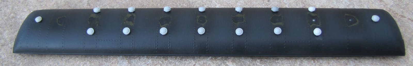
Interior of the 77-C-3, stock Athearn-Genesis painted - the power pickup wipers can be seen at the far light green bulkhead.

I removed the car end (easily done, as it's press-fit only), so that I can more easily work on installing the tailgate and marker.  I soldered some TCS #1219 32-gage wire to the resistor and the other LED contact to connect to the Athearn-Genesis roof lighting strip.  The truck power comes up through two metal contact wipers at each end of the car.  Actually the inboard interior wall of the men's and women's "dressing rooms" right to the ends of the main seating area's light strip.  I removed the lighting strip by unscrewing two Phillip head screws, so that I could more easily solder everything together.

The vertical side strips of the gate were modified to fit the Athearn Genesis 77-C-3 and were removed to narrow the gate.  Once the gate can fit into the opening at the end of the car, I glued it in place with Tamiya liquid plastic glue.

As the roof lighting strip contacts will be full track Voltage, I soldered into the light strip at that point, keeping the wiring up in the roof.  I reinstalled the car end and the lighting strip with the two mounting screws and pressed the car end back in place on the body shell.

Clip-leading to my power supply, simulating track power, I tested the LED marker to be sure it was working.

Closing Thoughts on V-Blogging


OwlMtModels Marker kit installed on a Cascade TTG 77-C-3, by Athearn Genesis
I'm going to wrap up SP 2436, Part 1, here.

Comment what you think about the videos, if they're helpful, etc.  I know I didn't use the best camera or have the greatest setup either.  I'm not sure how much, if any, more video footage I will use on this blog in the future.  The uploading and editing these two less-than 20 minute videos took over two days.  I might consider it for special projects, where still photos don't really get across what I'm doing.

I do have some footage of the window shades going into the SP 2436 for a Part 3 video, if there's interest in the community.  That will be in SP 2436 (Part 2) when it's ready.

Jason Hill

Thursday, September 15, 2016

Overview of 1950s Time Table Operation Session (Part 1) La Mesa Model Railroad Club

I thought today, I'll write and post on something a bit different than building models.

A while back I uploaded a video over viewing the basic 1950s Time Table & Train Order (TT/TO) recreation that La Mesa Model Railroad puts together every two or three months.

I joined the club in 1996 and joined the Operations Department in 1998, helping to set up for the nationwide group, known as ProRail to come and operate the layout over a weekend (24 hours).

Hopefully you'll all enjoy a look at how I see this fantastic layout, which is at its best during the regular TT/TO sessions: "It's like going to a zoo (museum) seeing the dragon (layout) in its cave sleeping most days (Public operations), but during a full TT/TO session the dragon's awake, flying around, and breathing fire!"

History of the Layout


SP Malleys in their natural habitat, lurking in the trees of the Tehachapi Mountains at Walong "The Loop".

For people that are not familiar with what the La Mesa Club has built over the last 34 years I'll describe some of the basic statistics of the exhibit.  The club decided several years before moving to the space in the Casa de Balboa building to build as accurately as possible the Tehachapi Subdivision of the Southern Pacific and Santa Fe "Joint Line" between Bakersfield and Mojave, California in HO scale.  This dream, from the start, was to be a fully working replica of the Tehachapi Subdivision as it looked and worked during the 1950s.

To have space in the building, it operates for the public 6 days a week (Closed Mondays) and usually has a few trains running from various eras.  Regular lap times are well over 1-2 hours depending how much of the railroad is open and how many crews are available on a given day.

Detoured Coast Daylight (Second 52) is passed by a very long (70-ish car) 800-series freight with a PFE block of reefers 

In many ways, the club has exceeded the original dream as the railroad was built, tweaks and changes to "The Plan" were made, increasing the complexity and scale of the model built.  Hundreds and thousands of more hours of research during construction of the model also means that the Operations Department, the core group of people researching the historical Tehachapi Pass, have learned more about how the traffic moved, what the sources and destinations of the traffic was, etc than they had originally planned.

History of the Real Railroads - SP and the ATSF on Tehachapi


The Southern Pacific built the railroad connecting the San Joaquin Valley and Los Angeles in 1876, only 7 years after the completion of the Transcontinental Railroad at Promontory Point, Utah, in 1869.  The Santa Fe Rwy signed trackage rights agreements in January 1899 to use 67 miles of Southern Pacific track over between Bakersfield and Mojave.


An Extra Westward Santa Fe freight pulls out of the 3-way meet at Caliente, locking Second 52 in the siding.

The layout now uses about 7500 sq ft of space on two levels.  On the real mainline about 2/3s of the 68 miles of track is double to allow trains to move unrestricted by opposing traffic.  The modeled mainline is about 30 miles long, about 50% of the modeled mainline is single track.  This requires trains to wait at sidings for opposing traffic to clear.  Using TT/TO operations, the trains receive orders from 5 station telegraph (phone) operators that copy verbal orders from the Dispatcher onto written orders using carbon paper.  Clearance Cards are issued once the complete set of Train Orders are assembled. These orders are issued to train crews and prescribe any changes that effect their operation for their train.  These orders may change schedules of trains, meeting points, number of sections, inform the crew of additional sections of scheduled trains, and providing for them to move farther against opposing traffic than if the orders were not issued.

In later years TT/TO was replaced on high traffic divisions, such as Tehachapi, by a system called Centralized-Traffic-Control, or CTC, This allowed the Train Dispatcher to removely control the signals and siding switches to route trains and increase traffic density on a section of railroad.

The Video -

I should mention that this video is about 25 minutes long, so grab a bag of popcorn and enjoy the show.


The opening and closing footage is of the club's San Joaquin Daylight pulled by a set of dual service F7 ABBA units.  I will at some point do some posts about the cars, and various upgrades and techniques I used on some similar MTH and SC&F models.

There's mixed footage of westward trains waiting at Tehachapi for opposing traffic to clear onto double track.  I didn't really get into helper operations or the variety of operations the 1950's TT/TO sessions have.  I hope to get into that more in the future.  The track work is still newly completed in these filmed views of Tehachapi.

There's about 7 minutes of our Train Order Dispatcher issuing orders and receiving OS reports of train movements.

Towards the end of the video footage, I show some switching at Caliente with SP 3259 assigned to the KI Local.

In future installments of this blog topic, I'll be covering various aspects of the 1950's operation at La Mesa Model Railroad Club.

Extra 4255 West in the classic vintage pose at the 'upper grade signal' above Caliente with a westward freight.

I'm going to leave this blog post here for now.  I have more material that I would like to go into detail on, but it would make this post WAY too long.

Jason Hill

Monday, September 12, 2016

SP 60-C-5s, (Part 1) SP 1005

In this series of posts, I'm working on some Soho 60-C-5 coaches.  The first two are both the same class, yet quite different cars as examples of what happened to SP and T&NO's large fleet of 60 foot coaches over the years.  Both the SP 1005 and the T&NO 777 are based on the Soho model of a 60-C-10.

SP 1005, 60-C-5 Chair

SP 1005 with window shades and replaced roof vents.

SP 1005 started life as Northwestern Pacific (NWP) 401 and was fitted as a "smoker" coach with a partition mid-car.  The NWP 401 spend her early carrier working north of San Fransisco Bay until 1935, when it was transferred to the SP and renumbered 1005.  Like all 60-C-5s it was built with transom windows of colored glass and end windows.

Here's the SP 1005, before I changed the roof vents.  The end-window can be made out in this photo as well.

In 1940, the SP was short of cabooses, so SP 1005 was reassigned and numbered into the caboose series as SP 998.  Mid-war it was decided that the SP needed more coaches to deal with the crush of the troop movements and was short passenger capacity.  SP regained her status as a revenue passenger car in 1943 by having 60-seats worth of second hand chair seats installed.  Only a handful of the SP 60ft coaches were equipped as chair cars instead of coaches, but didn't go all the way and get air conditioning.

SP 1005 lasted through the war and was one of the few cars that still retained its gas lighting in 1945.  I've not really tracked down any more data on the 1005 as it kicked around between various unknown assignments until it was photographed in Oakland in 1947 by E.R. Mohr, Pg 120 in SP Passenger Cars Vol1., by the SPH&TS.  The green glass of the transom windows were still intact in the photo, by 1950 most SP coaches and chair cars had these plated over.  The last being covered in 1952.  This was mostly because of problems with leaking in the transom windows.  The 1947 photo was only 6 months to a year after the SP changed to "Southern Pacific" lettering above the windows, so it's very understandable that this car wasn't a priority to repaint.

In 1952, the SP 1005 was retired.  A year later, it was reactivated as a caboose for the second time as SP 953.  Another car had taken over the Caboose SP 998 number.  By 1954 the 953 was retired again and what happened after that is unknown, it was probably scrapped at that point.

Modeling the SP 1005

Here's a Soho 60-C Coach in similar starting point to where the SP 1005 started

I started this project with a Soho 60-C-10 with transom windows.  My problem is by 1948-1952, when I model most of my equipment, these transom windows were becoming VERY rare.  I chose the 1005 because of it's somewhat unique history.  It would also fit well into my Tehachapi Mail (Nos.55/56) consist to mix up the regular 60-C-coaches, or in other mixed assignments typical of the "wandering" SP non-A/C coach after WW2.

Soho SP 1005, 60-C-5 in-process - Note the green glass in the transom windows.
I'm modeling the SP 1005 after its 1943 conversion to a 60-seat Chair Car, this means I do have to make some modifications to the "early" Soho Coach.  The car is painted Dark Olive Green and my standard mix of off-black gray for the roof and underframe.  "SOUTHERN PACIFIC LINES" decals are used on the car to show another car that hasn't been repainted since 1946.  Also, remember this car is pretty clearly not in the best condition.  It's been retired once already, and but for the needs of WW2, it would have stayed as a caboose.

Here's a photo to show off the Tamiya Clear Green painted glass transom windows

Windows were installed using clear sheets of styrene.  I masked off everything except the top 18" of the windows.  This leaves what will be the transom windows exposed.  I used Tamiya Clear Green to tint the upper glass a lovely green color.  Be sure to tint the inside of the windows!  This will help prevent scratches to the tint and also keep the mounting glue from de-bonding the tint as well.  Once dry, I installed the window sets with Testors Canopy Cement.  Be extremely careful to have the green glass and clear glass change fall behind the narrow header of the main windows.

The diaphragms are again from HiTech.

Underframe

Basic Underframe

John Ruehle made me a new underframe for the car.  John used a piece of 0.040" sheet for the main floor.  Then C-channel 0.185"x 0.150" was used for the main centersill.  Crossbeams of .070"x 0.050" I-beam were glued on to represent the floor supports.  This underframe doesn't have any of the diagonal bracing that the 69-BP-30 (SP 5199) or the rest of the SC&F kits have.

John mounted passenger brake "UC" type gear on the bottom of the car.

Electrical Generator was already fitted to the underframe

Looking at the SP 1005, with its "rare" gas lighting by 1947, certainly rare by 1952, I will be adding the gas tanks.  However, I will probably add a battery box, because I'll be adding the OwlMtModels 10002 Gyralite Marker Light.

Styrene shims added to bolster of Walthers 920-2124 on SP 1005.

I shimmed the bolsters and installed a sheet of 0.02" styrene across the top bolster of the Walthers 8ft Pullman 4-wheel trucks to result in the right coupler height.  I plan to fit the car (in Part 2) with my standard LED lighting strip and OwlMtModels Pyle Gyralite marker and tailgate kit for end-of-train service.

Window Shades

Completed window shades installed in the SP 1005

Window shades for the 1005 are made from manila card stock file folders.  One folder will do about 30-50 sets of window shades.  I don't use normal 3-5lb paper because, unless painted, it is too translucent for use with the LED lighting installed, even at lower settings.

Cut a strip of card stock a scale 24"x 50'6" and make pencil markers where the window columns are across the full shade.  I then mark where I want the window shades to be cut off at.  This will be on average, make the shade 12" high, however I like to make somewhat random cross cuts with a Xacto to show passengers using the shades and moving them to where they want to be.  These horizontal cuts are then connected with small vertical cuts to make a prepared window shade.

Abbreviated shades to keep the green transom windows clear. Tamiya tape used to mount the shades.

Remember that cars freshly out of the coach yard should have all their shades nicely trimmed 1-3" below the top edge of the window, or whatever the railroad considered "standard dress" starting position.  A car ending its trip will be all over the map, some shades high, some low, some in the middle, some unused if the seats were empty the whole trip.

Once trimmed to length (This time I was also making standard longer ones for my SP 1050's window shades) I used 1/16" wide by about 1/4-3/8" long strips of Tamiya Masking Tape to hold the shades in place.  The tinting on the windows was actually thick enough, once the mask was removed to make a nice stopping ledge for the shade material to catch on.  The tape was then applied with the end of a knife blade vertically where the window columns are.

Bathroom window covered with Scotch Tape

The toilet annexes will have etched glass or prism glass, I use standard Scotch Tape (not the magic clear stuff), so that when I apply it to the clear plastic windows it will remain foggy.

"Globe" Roof Vents

Here's the 1005 with new MDC "Globe" vents

I removed the Soho stock Utility Vents over the main seating area.  I still need to remove the vents over the car ends.  There was a slight mishap and I scratched the roof paint pretty badly there in the center of the car.  When I do the additional end vents I'll touch up any other scratches.  The square holes left from the old vents were roughly in the right place on the roof, so I used my ~0.085" drill bit in a pin vise.  As always drilling through brass sheet, be careful when 'breaking through' with the tip as the drill will tend to catch.

The MDC vent pieces were easily glued into the holes with ACC.  Make sure not to put the car floor back on for a day or so after gluing.  This will allow the glue to "gas-off" and not fog the windows.

Interior

Here's the SP 1005 with the seating strips of PSC 33312.2 Chair Seats

Because the SP 1005 was pulled back into service as a chair car, she lost her original 72-seat coach configuration.  Instead a 60-seat chair plan was used, probably from second hand chairs from other 60-CC-1s upgraded in 1941-42.  Trying to find exactly the right seats is a bit challenging.  For this car I'm using Precision Scale Co. #33312.2 chair seats were used and mounted to a strip of 0.03"x 0.188" strip styrene was used to space the seat pairs apart.  The inside of the car sides have flanges, which add strength, however they do make the installation of interiors a bit tricky.  Once glued up, these strips of seats will be able to be easily mounted to the inner ledge of the car side.


The 15 rows of seats are evenly spaced every 3.28 ft over the 50'4" length of windows.  In laying this out I come to find out that the car is about 2 feet too short, all in the toilet windows section of the car.  That doesn't really effect the modeling of the interior though, just interesting to note.  The last pair of seats are showing in the floor plan reversed.  These would have been the walk-over type seats, possibly from the A/C'd 60-CC-1s, which new seats in 1942.  SP had a way of reusing second hand seats on older cars.

The center isle will be purposely left open for access to the lighting strip in the roof.

LED Lighting

An example of a car I installed this type of lighting in

I don't plan to mount the interior seats strips until I have the LED strip installed and lead wires for the trucks and marker light are installed.  As a sneak peek, here's the light strips that I make myself.  I use 0.100" x 0.250" styrene strips as a backing support for the LED light strip.  The leads are easily soldered onto the ends of each 3" section of LED strip.

LED lighting components

In the center of the LED coil, is a 3" strip for the SP 5199 project I'm working on, and above that are two 6" strips for the 60 and 70 foot coaches I'm working on at the same time.

Beauty shot in closing here

That does it for this part of the SP 1005 Build.  In SP 60-C-5s, Part 2 T&NO 777 I cover building a car without the green transom glass windows and more detail of the underframe construction.  Please follow to be notified when I post the next blog update!

Jason Hill

Related Links:
Of some interest is Sunset Import's new announcement of plastic 60-C-5s coming to HO, follow this link to my blog post with my thoughts on it. GoldenGateModels Harriman Cars in HO

Or you can follow this link to my blog on building the SP 2701, a 60-CC-1 (Part 1) from a Model Power Coach

Friday, September 2, 2016

Modeling SP 2701, a 60-CC-1, from a Model Power coach (Part 1)

Model Power many years ago produced a "Harriman" 67ft Coach with arch-roof.  These cars are still a good stand-in for several classes of cars.  I'll be covering the options of how to use the MP Coach as a stand-in for both the SP's 60-CC-1 Chairs and 60-C-3/4 Coach class cars.

SP 2701, 60-CC-1, modeled as it appeared in Oakland during March 1953 with a stand-in Model Power 67ft coach.

The cars were 60 feet long over the "Endsills" which were the inside of the doors.  The vestibules, doors, steps, and end sheets of the cars were never counted in SP and UP Common Standard Designs. Only the usable floor space inside the car was counted and used for the Common Standard class.  This is why the Model Power car shows a length of 67 feet, is they're counting the length to the end-sheets of the model, over the doors.

Here's a cheap Ebay grab for more MDC kitbashing fodder!  I usually cut them up for other projects.

Model Die Casting (MDC/Athearn) 60 foot coaches are not correct in that they're measuring over the 60ft body length, not frame length, so these models are 7 feet too short!


Prototype Car History


SP's first two 60ft steel coaches, SP 1806 and SP 1845 were built in July 1906 and July 1909 and assigned to class 60-C-1 and 60-C-2 respectfully.  These cars continued the SP's wooden coach design of a single 29.25" window at the "West" end of the car, then eight 4'3.5" windows in the middle of the car, followed by two 29.25" windows on the "East" end of the car.


SP 2810, ex-1806, the first steel passenger car on the SP.  Also the only 60-C-1, became 2810 in 1953 for express service.

The next two classes of Common Standard coaches (60-C-3 and 60-C-4) were built to the same standards as the 60-C-2.  These car orders totalled 219 cars for the Pacific Lines and 35 (60-C-4) for the Texas Lines.

SP 2310, an example of the later 60-C-5 through -10 class cars.

Following 60-C-series Coaches for the SP were of paired window design and will be covered later.

The 60-CC-1 Chair Cars were built in 5 lots of cars starting in 1909 for the IC and UP.  The SP's 52 cars were in the fourth lot, Lot 3840, delivered between November 1911 and April 1912.  These were in two number series on the SP roster.  SP 2500-2530 (31-cars) and CP 2700-2720 (21-cars).

The 60-CC-1s had 9 large windows with 12.25" columns between them and only single smaller windows at the ends of the car.  SP's following classes of 60-CC's were of paired-window style construction, not the picture-window style of the 60-CC-1s, and will not be covered here.

Model Power 67ft Coach part way through rebuilding as a 'stand-in' 60-CC-1 as SP 2701.

The MP car is actually a couple of feet longer than the KenKidder (SP 2810) or Soho (SP 2310) cars shown above.  This is one reason I try to number my odd-ball "stand-in" cars as other than 'general service' cars where you'd be seeing them next to more correct models.  I'll cover modeling the SP 2810, ex-1806, in another post in more detail.


Getting Started


The main issue with both the MP and MDC models is that the manufactures basically mixed the dimensions of the windows and columns between the 60-C and 60-CC class cars.  This results in the MP car having no room for the second single window at the East end of the car if it was to be a 60-C-3/4 and only 8 large windows if it was to be a 60-CC-1.

Because the look of the car appears to be more of a 60-CC-1 without the second East end window, I've elected to number my stand-in model as one of these, ignoring the missing 9th large window.

Starting with the Model Power car out of the box, I disassemble the whole car into its basic parts.  A very long screw-boss extends from the center roof of the car through the interior, weight, and underframe to hold the car together.  It also is visible in the interior of the car, through the windows.  I don't care for this 'feature' at all.  So one of the first things I do is cut that out.  This leaves a hole in the center of the floor.  There are also several other holes in the floor, just inboard of where the trucks bolsters will mount.  Again, I'm not too worried about those at this time.  Later interior and underframe construction will cover those.

The window glass comes out and the trucks pop out of the rudimentary underframe, leaving the body and roof.  Model power cars are what I consider a "budget" model.  These should be able to be found on Ebay for maybe $10 at a good price.  Swapmeets are the other good place to get them.  Perhaps estate sales at your local hobby shop.

Painting


Once the car is stripped down to basic components, I tried to strip the "US ARMY" lettering off the model, this has some success, but I was also trying to avoid getting into the poor quality plastic carbody.  Old Rivarossi HW cars, such as their 12-1s and ATSF Diners and Cafe-Observations have this problem too.  The old Model Power paint hopefully will help protect it somewhat from the lacquer StarBrand Dark Olive paint.

I painted the body pretty early in the rebuilding as there wasn't a lot to change on the body.  I decided on this stand-in model not to replace the grab irons.  The steps would be black, so I left those off until painting of the body was done.  The roof as well would have the vents repositioned and then painted off-black, so those would wait as well.

The body was painted StarBrand SP Dark Olive and then gloss coated for decalling.  I chose to model SP 2701 as an interesting car to model because of it keeping the "SOUTHERN PACIFIC LINES" lettering into the 1950s.  See page 58 of SP Passenger Cars Vol1., published by the SPH&TS, for a nice view of the SP 2701 in Oakland on March 16, 1952 by W.C. Whittaker.

The SP 2701 is also interesting in that it didn't get air-conditioning, and kept the lettering as "CHAIR" under the reporting marks into the 1952 photo.  Most SP Chair cars were upgraded to "Deluxe Chair" during the period between 1936 and 1941 for service on premier and higher rated secondary trains like the Owl and West Coast.  The seating in the 2701 still looks like it has the nicer seating with head-rests, so it would appear that the SP 2701 is still internally a non-A/C'd chair car.  Also it did not warrant get repainted after the June 1946 change in lettering until at least March 1952.

I plan to use this car in various assignments, anything from a rider car on a special Pullman movement to a rider on an SP Mail & Express train.  It could even show up on a regular mail train (Nos.55/56, the old "Tehachapi" Mail for example) in place of a standard non-A/C coach.  The non-A/C'd chair cars were defiantly in a weird place in terms of assignments after WW2.  I could also see them being assigned other 3rd rate passenger trains and locals, such as the Rogue River, Shasta, Suntan Specials, and other short haul trains that wouldn't rate getting nicer A/C'd coaches or chair cars.

Mechanical Changes


The partly rebuilt underbody showing the basic mechanical changes.  (Left to Right: weight, bolster & frame, steps)


I started with the mechanical changes to the car.  Once painted, I glued in the end steps from a cut up MDC coach.  These were cut off about 18" inside the endsill of the car, so it would 'key' into the sides of the car for a good joint.  ACC-gap filling glue was used for this, as the plastic wasn't a tight friction fit.  The joint at the endsheets to the end of the underframe sections was also glued at this time.  The floor of the car is pretty high, as the original Model Power underframe encased a steel weight above it.  I scrapped the steel weight.

After weighing the parts of the car with the Walthers (920-2124 - think that's the current number) Pullman 8ft 4-wheel trucks that will be used, I get a rough idea of how much the model will need to weigh.  I use the La Mesa Model Railroad - Car Weight Standards chart for this.  - "A 70ft car of non-metal construction should weigh 6.25 oz. if it rolls on a 1.5% grade."  Checking against the weight for the same car if metal construction shows it could be as high as 8 or 9oz.

This is worth checking because as a passenger car, it might be run with other 'heavy' brass cars.  The lighter car should be ok, however with diaphragms the cars are actually in sprung, physical contact with eachother.  Plastic cars in those situations I've found need to weigh a bit more than the standard "Non-Metal" car weight.  The 1.5% grade figure is pretty easy to get with the Walthers trucks and being sure to lightly dress the bearings with an axle reamer.

A new sheet lead weight is cut to bring the car up to a weight of 6.9 oz without the interior parts or underbody detailing.  This weight is 1/8" sheet lead, 1.3" wide (just fitting between the lower side sheets of the model), and 4.25" long.  In this configuration the weight fits cleanly between the wheelsets of the trucks.

Kadee 0.015" Washer and coupler box installed.  The car sits low, so I don't want the weight over the trucks.

The next step is to layout the centersill of the car.  I use 0.250"x0.150" styrene strip for this.  The strips extend from the inside edge of the MDC frame ends to the weights in the center of the car.  I stopped the frames on this car short of the large holes in the MP floor.  That will be easier to cover later if I don't have frame bits in the way.

Top view of Walthers (920-2124) Pullman 8ft 4-wheel truck with styrene block added for standard 2-56 bolster mounting


Bolster Center marks are scribed into the floor a scale 45' apart, or 1.625" in from the end of the car, over the door frame.  Standard center punch, drilling and tapping for 2-56 truck bolster screw is done and a Kadee 0.015" fiber washer is added to the bottom of the bolster to provide a good pivot and bearing surface away from the styrene strip frame.  The trucks are modifed with a 0.115" thick block of styrene to adapt it to using a 2-56 screw.


The wheels have also been regauged and axle reamed lightly to ensure they can roll easily.  ACC used to secure the wheels on the axles after regauging.

Bottom view of Walthers 8ft 4-wheel truck with styrene bolster block added.

I will go over more about that trucks when I get into the lighting and interior.

Diaphragms & Couplers


End detailing was mostly limited to installing the Hi-Tech Diaphragms - ideally use Common Standard or Western Short diaphragms.  The diaphragms were a bit too tall to fit solely on the car end, so I went with a styrene extension to the end of the car.  This was a 0.550" long piece of 0.135"x 0.030" strip styrene (Evergreen) ACC'd above the end of the car to catch the upper leaf spring of the diaphragm.

Diaphragm installed with upper support of styrene to "catch" the upper leaf spring.

The couplers were mounted next in my standard method of finding the right coupled length.  This is done by mounting the coupler after the diaphragm and using the inside of the pulling face of coupler to set the distance back from the end of the car.  Then drilling and mounting the coupler box with a 2-56 screw.

Slightly more of a side view of the Diaphragms and coupler.

I usually mount the Hi-Tech diaphragms with the leaf springs "legs" or body mounting side a bit (about 0.03 or 0.04") closer together than the instructions call for.  This creates more arch in the leafs and pushes the striker plate (moving part) of the diaphragms out farther, giving more flexibility to the diaphragms while tracking around curves and coupling to cars with tighter diaphragms.  Some models don't have enough flexibility in the diaphragms.  If they "Go solid" this will cause many derailments and other problems.

Couplers and Diaphragms when viewed from below

The couplers are standard Kadee Whisker Coupler versions of the old No.5 with the new No.242 boxes.

Roof Modifications


Because this car does not have air-conditioning, it is both easier and harder to model.  It's easier in that I don't have to deal with all the extra A/C equipment under the floor of the car.  However, this does mean that I need to work on the roof vents.

Original positions of Model Power centerline roof vents, before remounting them.

The default Model Power car comes with a line of vents down the centerline of the roof.  Some of SP's 60ft cars did have this, but not the 60-CC-1s such as the 2701.  These roof vents were removed with a pair of flush cutters, so most of the original holes were plugged with the remnant of the centerline vents.  Some light filing and sanding was required to get the plugs even with the contour of the roof.  On two holes the flush cutters tended to pull the vents out, leaving a hole.  A bit of styrene and putty works to fill these and then re-sand and file to shape.

I measured off of an MDC roof where the offset roof vent lines should be.  They look about right to my eye.  Then scribed a line lightly between the pairs of rivet rows from the side of the roof 0.480" to 0.485" up onto the roof with my calipers.  I in fact, tried to keep these scribes very short to hide under the roof vents when mounted.  These vents were only fitted between the pairs of large windows on the side, centered on the columns.  Because the MP car is one window shorter than the prototype car, there will only be 7 pairs of vents offset from the car centerline.  There were also vents over the end-isles, just inboard of the endsill wall to the vestibule.

Filled and sanded Centerline Vents and new SC&F vents installed.

I chose to use my supply of extra SC&F resin Globe vents on this car.  MDC/Athearn has a nice selection of Globe vents included with their cars.  As I've built a fairly large number of models, I have a fair supply of vents from swapping them between different projects.  My next vent rebuilds will have to use the MDC ones.  Other Globe type vents are available in brass.

Crosshair scribes were made centered between the rivet rows over the window columns with my carbide scribing tool and then at the crossing point,  I used the scribe to press in a center mark for drilling out the holes.  A No.50 drill bit works nicely to make the holes for the SC&F vents.

New Roof Vents mounted

The vents were glued in place with ACC.  Keep an eye on the angle of the vents to the roof and also take care to keep them in a good straight line.  If the holes were a little bigger than the part, that helps to adjust one or two of them to keep them in line.  I also had one or two holes that wandered... so again, use a No.11 Xacto blade to move the hole over slightly to line up that vent.

Lighting


I plan to do subtle lighting in this car, so I made a reflector of 0.005" white sheet styrene to bounce the light back into the interior of the car.


Using another piece of 0.100"x 0.250" styrene strip to make the "spine" for my home-built LED lighting system.  I then ACC the sections of LED Lighting Strip to the spine, which is then glued into the endsill walls at the end of the car's main seating area.

Night shot of a car I equipped with the same type of LED lighting as SP 2701 will have.

That does it for the SP 2701 for now... Next time I'll work on adding the rest of the interior parts, such as bulkheads for the restrooms, longitudinal seating benches, and main chair seats.  The underframe detailing will be addressed, as the battery box, electrical generator, and brake rigging will need to be added.  Also, I'll be installing the pickups to bring track power up to the lighting strips and an OwlMtModels #10002 "Tailgate Gyralite Marker kit for operating the car at the end of the train.


That does it for now.... Enjoy this picture of the real SP 1919 at Niles Canyon from 2009!
Follow this link to Modeling SP 2701 (Part 2).

Jason Hill

Follow this link to my SP 1005, 60-C-5 (Part 1) build blog.


Thursday, September 1, 2016

Mistakes in Modeling - Part Oops!

Well, we all make mistakes...


Can you see the mistake?  I bet you'd never know.. but now that I know... it's REALLY ANNOYING!

A few weeks ago as I was finishing up a PSC 60-P-5 model of SP 4261 for a customer.  I reviewed the various RPOs I was working on to see which ones might need the 3D printed interiors.  I was looking forward to designing one for the 4261, as its unique interior layout would show off the double letter case on each wall between the windows!  I was reviewing the car's history in SPH&TS SP Passenger Cars Vol.3 and came to the horrifying realization that I had made a mistake in the car!

Car Backround


The SP 4261 was the only car in SP's last class of 60 foot postal cars.  Her sister cars were sent to UP, and for some reason the SP ordered one car following the style of those cars.  The SP 4261 has its letter cases mid-car, with the windows towards both pairs of side doors.

One can only assume that it was because this car was the odd ball, but it was retired from active RPO service in 1936, while most of her older sisters stayed in service many more years.  The car was then placed in Storage Mail service.  When RPOs were stricken from the fleet of active RPOs and stripped of their working capacity, i.e. Catcher Arms, Sorting Racks, Letter Case, etc. they would pretty quickly have their "US MAIL RAILWAY POST OFFICE" lettering painted over.  Baggage cars usually had lettering for BAGGAGE and RAILWAY EXPRESS AGENCY on their sides to indicate what service they were in when the RPO lettering was painted out.  Cars in dedicated Storage Mail service would have "US MAIL STORAGE CAR" lettering applied in place of the RPO lettering.

The Error


The 4261 in 1936 would have been in Gold Leaf lettering "SOUTHERN PACIFIC LINES" when last lettered as an RPO.  The model that I'd finished lettering was done for the post-1946 "SOUTHERN PACIFIC" style lettering.


The SP 4261 should look something more like this picture of my in-progress SP 4404....

The Fix


Well, the customer wants the car to be the way it should look in the 1950-1953 era for operations.  So there's only one thing to do.  Not wanting to try to strip the car and repaint the whole thing, I masked off the carside where the offending lettering was.  I placed the masking vertically near a rivet line, so any stepping of the masking edge would be hidden or look like a joint in the car siding.  I shot a fresh batch of StarBrand SP Dark Olive and covered the overcoated decals.

I've tried stripping or just lifting off the bad decals in the past.  If they've been properly applied and set completely, and then overcoated and sealed they're is NO WAY it's coming off without completely messing up the rest of the paint job on the car.  It's better to patch over completely finished and sealed decals.  These decals are extremely thin and I will be placing new lettering decals over the area, so I'm not worried about anyone "seeing" the old lettering... even if they did it's prototypical!... The real car probably still had "RPO" lettering under there too!

It took an afternoon to reshoot the car and a few days of drying between the painting and glosscoating.  I have plenty of extra Storage Car decals laying around, as most models I've done are using the "BAGGAGE" and "RAILWAY EXPRESS AGENCY" lettering for baggage-express cars.

Back on Track!


All better, Storage Car 4261 will soon be ready for service!

Here's the relettered and corrected model of SP 4261.  While I'm sad that I don't get to do a car with all the cool interior and full length lighting to show it off... at least this unique car will continue to be a very unique car in Storage Mail service on trains like the Owl (Nos.57/58). - (Link to Modeling the Owl - Part 1)

I'm sure this won't be the last model that I'll have to do something to "Fix" so I thought I'd share this. I hope that this encourages everyone out there to not be afraid to change your models to keep up with the new research that is available to us now!

Jason Hill