Saturday, November 26, 2022

Car Standards - (Part 1) - Weight, Rolling, CG Allowances & Diaphragms

The following is an excerpt from the LMRC's Car Registration Mechanical Standards.  The data here goes back to at least 1996 when I joined the club.  The first 3-4 years, I was involved in the Car Department learning all the aspects of proper freight car construction to club standards for excellent operational qualities.  In the 2010s, when I designed the F-50-series kit for OwlMtModels, these standards formed the basis for all the mechanical design for the construction of the new cars.  Now, 25+ years later, as I'm continuing to build my SP Jawbone Branch and additional cars for it, I'm still using these standards on the car kits I build.  Cars built to these standards can run on any layout, anywhere and preform well.

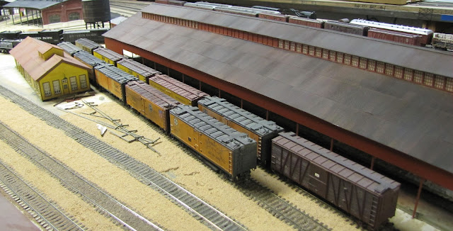
Car Shops at Bakersfield, LMRC photo Oct 2016

For now, I want to specifically look at the relationship between car weight, rolling qualities, and center-of-gravity in the cars. 

Layout Standards


I will also say that these car standards are paired with the right-of-way construction standards of the layout.  Full compliance with both of these standards allows for train lengths to climb to nearly 80 cars upgrade and 120-140 cars downgrade.  Of course it takes a good crew to take a train over the railroad without any problems, physics still has a bite if you do anything too fast, or pull something stupid.

Three AC's work upgrade with the Mojave Shorts East at Caliente.  Photo circa 2009, Jason Hill collection

The curves at the club are 48"R minimum with 1/4"-3/8" tangent offsets with 12" long spiral easements.  Grades range up to 2.3% on the steepest parts of the main grades.  Limits of 39 cars without helpers on the ruling grades.  At 40 cars and above helpers need to be cut into the ascending trains.  Around 70-80 cars descending trains also need to have a helper to keep the cars in the train from rolling down against the road engines and causing excessive buffing force, which will eventually push hard enough to derail and buckle the head-end cars sideways.

LMRC Car Standards


Starting at the Weight section...

Weight


1. The minimum weight for any car is 3.25 oz. "Inspected" rolling stock (excepting Locomotives) must conform to NMRA Recommended Practice RP20.1, with an absolute minimum weight of 1/4 oz. below or 1/2 oz. the calculated recommended practice (see two weight tables, next page).
2. Track slider (cleaner) cars should be weighted to the maximum weight for their car length and rollablity category, and roll (bench tested) with the track slider disengaged from the rail contact.  Finally, they must be successfully track tested on the railroad with the track slider (cleaner) fully engaged with the railheads.
[3.] Registered equipment must be weighted according to the appropriate weight/body length/rollability/ tables below.  The table tolerance is stated above (Weight 1.).  Further allowances should be made according to the paragraph (Allowances to Weight) below.  Every effort should be made to construct the equipment to its table "target" weight.  Category I Freight cars regularly used in passenger service with predominately Cat. II equipment (e.g. express cars), MAY be required to conform to the Category II weight requirements to ensure reliable operation.
[4.] Model loads added to rolling stock should weight as little as possible and be removable, except as provided in paragraph 'M' below, (Summery of Paragraph M, basically TOFC/COFC and modern containers should not be weighed.  Only bottom containers in double stack well-cars may be weighted).

Allowances to Weight

1. Weight allowances to equipment may be made from the referenced weight tables at the discretion of the Car Department Foreman, on a "proof" basis- as follows:
    a. Cars having a 'Center of Gravity Index' (CGI) Less than 35 degrees (CG35), NO weight reduction.
    b. Cars having a CGI of 35 (CG35) or MORE: allow 0.25 oz. (1/4 oz) reduction to the charted weight requirement for every full 5 degree increment to the CG Index above 35 degrees (CG40, CG45, etc).
2. There is no limit to the maximum weight allowance applied under this formula as long as the car meets all the requirements of Section III. This MAY even be applied to the points where the formula brings the car below the 3.25 minimum weight requirement- subject to testing and approval by the Car Dept Foreman.

Roll-ability

1. Rolling stock (excluding locomotives and other track powered equipment) must initiate spontaneous motion on a grade of 2.5% or LESS and have a smooth, steady, uninterrupted roll for at least one full car body length.
2. There is no rollability allowance/exemption for freight cars in regular interchange service.
3. Cabooses, passenger cars, unit trains and MoW cars are not in regular interchange service and MAY be exempted at the discretion of the Car Department Foreman.

Center of Gravity


SP 32451 being built with lead strip in the centersill to keep weight lower to the rails.

1. Cars should be constructed to obtain the lowest center of gravity (NMRA RP 20.1)
2. ANY weight added to the car to make its required weight should be kept as low as possible (RP 20.1).
[3.] The center of gravity of each piece of rolling stock (locomotives excepted) shall be determined on a Protractor or Tilt Table and noted as its Center of Gravity Index, expressed in degrees. i.e. CG35 (or CGI-35). This shall be the farthest deflection from the normal upright (0 degrees or vertical) position to which the car can be tilted from the flat, level, horizontal surface (90 degrees) on which it stands without tipping over.  This will be determined by using a vertical protractor arm moving against the flat vertical side of the car, as the car is tipped sideways, the protractor pivot point center coincident with said horizontal flat surface.  Adapter blocks shall be used to establish a flat plane for the measurement  of equipment not having flat sides.  A high CG index number indicates a low center of gravity. i.e. CG90 (or CGI-90, alt CG=90).  Confusing notations like CGI90 are to be avoided.

Tables


Category 1:  Cars of Predominately Non-Metal Construction

Table of car Weights (ounces) by carbody Length (scale feet), versus Roll-ability (Percent of Grade).

% grade >        1/2%        1%        1.1/2%        2%        2-1/2%        Max
Car Length (Scale Feet)
30'                    3.25oz      3.25          3.25        3.5            3.75          4.0
35'                    3.5            3.5            3.5          3.75          4.0            4.25
40'                    3.5            3.5            3.75        4.0            4.25          4.5
45'                    4.0            4.25          4.5          4.75          5.0            5.25
50'                    4.5            4.75          5.0          5.25          5.5            5.75
55'                    4.75          5.0            5.25        5.5            5.75          6.0
60'                    5.0            5.25          5.5          5.75          6.0            6.25
65'                    5.25          5.5            5.75        6.0            6.25          6.5
70'                    5.75          5.75          6.25        6.5            7.0            7.25
75'                    6.0            6.25          6.5          6.75          7.25          7.5
80'                    6.25          6.5            6.75        7.25          7.5            7.75
85'                    6.5            6.75          7.25        7.5            7.75          8.0
90'                    7.0            7.25          7.5          7.75          8.0            8.25
95'                    7.25          7.5            7.75        8.0            8.25          8.5
100'                  7.5            7.75          8.0          8.25          8.5            8.75

Category II: Cars of Predominately Metal Construction (Brass Passenger Cars)

Table of car Weights (ounces) by carbody Length (scale feet), versus Roll-ability (Percent of Grade).

% grade >        1/2%        1%        1.1/2%        2%        2-1/2%        3%        3.5%
Car Length (Scale Feet)
40'                    5.0 oz       5.5            6.0           6.5           7.0            7.5        8.0
45'                    5.5            6.0            6.5           7.0           7.5            8.0        8.5
50'                    6.0            6.5            7.0           7.5           8.0            8.5        9.0
55'                    6.5            7.0            7.5           8.0           8.5            9.0        9.5
60'                    7.0            7.5            8.0           8.5           9.0            9.5        10.0
65'                    7.5            8.0            8.5           9.0           9.5            10.0      10.5
70'                    8.0            8.5            9.0           9.5           10.0          10.5      11.0
75'                    8.5            9.0            9.5           10.0         10.5          11.0      11.5
80'                    9.0            9.5            10.0         10.5         11.0          11.5      12.0
85'                    9.5            10.0          10.5         11.0         11.5           12.0     12.5
90'                    10.0          10.5          11.0         11.5         12.0           12.5     13.0
95'                    10.5          11.0          11.5         12.0         12.5           13.0     13.5
100'                  11.0          11.5          12.0         12.5         13.0           13.5     14.0

Jason's Notes & Comments


I have several thoughts and comments to add about the standards which were noticed and not fully codified as of 2022, but I will list them here in form so they can be implemented if desired.

Notes on Allowances to Weight


I will say that the allowances to the weighting is one of the most important aspects that differentiates LMRC's 1990s standards from the typical NMRA weight plan.  

Proto2000 AC&F Type 21 8k gal tankcar, which can be improved by changing the weighting plan.

Models such as Proto2000 tank car kits have four steel weights held fairly high in the tank's body.  Fully one or two can be removed if the weight is converted into lead strip or bars held in the center frame and below the lower weight in the tank.  This will lower the center of gravity index by about 10-15 degrees, bringing the car barely passable at 30 degrees to 40-45 degrees, which then starts to allow additional weight to be removed from the car: 1/4oz from the extra 5 degrees beyond 35 degrees, and probably 1/2 oz from the Proto2000 trucks rolling at 1 or 1.5% grade.

Athearn RTR 65ft gondola weighing only 3.5oz, but with the allowances below it doesn't need extra weight.

Likewise the Athearn 65ft Mill Gondolas can be allowed into service without adding extra weight to the underside of the car due to the metal frame, resulting in a full 120 degree CG, yes the car can be 1/3 inverted and it will self-right to its wheels!  No need to weight it up to 5-6 ounces!

Passenger Cars with Diaphragms (Narrow/Standard)


I'm going to expand a bit on the diaphragm discussion as used on plastic (Cat. I) cars, typical of modern models on the market.  For operations on 48"R curves with spiral easements, ideally the mating striker face of the diaphragm should be even with the inner pulling face of the coupler knuckle.

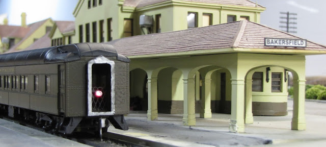
Walthers plastic HW Pullman with silver Sharpied striker plate and OwlMtModels 10002 Marker Light installed at Bakersfield depot, 2013 photo by Jason Hill

The function of diaphragms needs to be considered that "weird" interactions between the cars occur which do not with cars without diaphragms.  Basically, when a standard car derails, we look at the end that derails; the wheels, gauge, truck tension, etc.  However, on coupled passenger cars with diaphragms the troubleshooting thought process needs to basically be reversed.  Tension can be transferred through the bodies and throw the far end of a car off the track resulting from a binding of the diaphragms.

This occurs because the model diaphragms proportionally have way more physical force able to be applied to the car body than the prototypes do.  Real diaphragms only have a few hundred pounds of force being applied by their tensioning leaf springs against the striking faces, compared to car bodies that weight in the 30-80 ton range.  On the models we have cars that only weigh 7-12 ounces, but diaphragms that can bind-up and go so far as to provide an almost solid pivot point against the carbody, where the prototype diaphragm would just tear itself apart.  On the models we instead see a derailment.

SP 5199, SC&F kit built with Hi-Tech Diaphragm with a little extra spring distance.

This is why I ideally install the diaphragms to just barely touch.  Ideally the strikers can just contact and any compression forces applied will tend to pivot the other side to press outward roughly keeping the diaphragm from "opening" up visibly on the outside of the curve.

Passenger Cars with Full Width Diaphragms (FWDs)


Full-width diaphragm installed on HW Baggage car - lots of edges to polish with diamond file.

With the introduction of the MTH and BLI plastic Daylight passenger cars with FWDs, some problems were found during operations.  Even though the cars weighs were sufficient for the Cat.I mechanical standards.  However, Lead weights were installed to bring additional weight into the carbodies so the rubber diaphragms will compress better and not push enough to derail the cars.

One of the first steps I found was that the striker plates had micro-burrs on them, around the edges of the metal.  I polished them with a fine diamond file, creating a slight beveled edge to prevent catching against the coupled cars.

In Closing


Blasting through Caliente, No.52 attacks the ruling grade of Tehachapi, circa 1951. - Jason Hill photo

Additional information on wheels and couplers are a bit outside this post's scope.  If there's interest, I can talk about those aspects in a later post.

Jason Hill

Related Articles:


Wednesday, November 16, 2022

Modeling SP 32451 (Part 2) - Working on Sunshine B-50-15 Resin Kit


SP 32451 painted and progressing along.

Time for some updates on the Sunshine B-50-15 construction progress with adding grab irons and ladders.

Grab Irons


For this car I'm using the grab iron jig from OwlMtModels F-50-series flatcar kit.

These jigs work well to make more grab irons after the basic number of grabs to complete the flatcar.

I drilled the lower end grabs at about a 45 degree angle.

These lower end grabs need to be mounted right along the bottom of the steel ends.  This makes them exceptionally difficult to drill.  Also in the photos, the grabs are "Drop grabs" which are bent down below the lower edge of the car end.  So instead I drill the legs at an angle to make more secure glue anchors for the legs.

Another view of the end grabs installed and then bent into the final position.

Once the grabs are installed with ACC/CA glue, I bend them into the final position.

Ladders


Plastic ladders desprued, prepped to install.

The Sunshine kit comes with a sprue of plastic ladders.  I carefully cut them off the sprue with my sprue cutters and prepared them to install.

Side ladder ACC/CA'd in place.

I applied glue to the face of the ladder brackets on the body.  I used a piece of square steel to weight the ladder and press the ladder in place.

Completed Ladders in place.

Once the ladders dried, here's the view of them in place with the end grabs in place as well.  I also mark the center of the end at the top to match to the center of the roof.  As the roof will be a smooth mating plane, there will be no indexing of it outside of by eye and glue.

Gluing Roof On


Pencil mark showing how to center the roof.

Here's the roof resting in place showing alignment.

Other end with the roof centered.

End Placard Boards


End tack boards glued in place per photo locations.

End of car ready for paint.

Side view of the car at this point.

Ready to have the doors installed.  The doors were pretty easy to cut out and glue in place with the ACC/CA glue.  Unfortunately, I didn't get specific photos of the unpainted doors installed at this stage.

Bolster Covers


Bolster cover plates installed.

I also marked the center points for the stirrup steps with a pencil and then center pressed my carbide scribe into the center points.  These depressed points will still show after painting so I can see where to drill the holes.

Centersill Weight


Center cross beams caps glued in place.

I probably should have reversed a couple of these steps, but I went ahead and glued the center crossbeam caps over the centersill before I installed the centersill weight.  Thankfully this didn't cause too much trouble.

Centersill weight glued in place with thin ACC/CA glue.

I was able to slide the weight strip in from one end, over the bolster and under the center cross beams.

Second weight and double-rubber banded in place

Once I flowed thin ACC/CA glue around the weight from one bolster, I set a second weight that I'd cut to fit on top of the underframe, and then double-wrapped two rubber bands around the body.  The second weight is acting as a spacer to keep the thin glue from wicking up and gluing the rubber band to the centersill.  The second weight is also acting as a focusing block for the rubber bands to press only on the weight in the centersill, not on the resin flanges of the centersill.  This way the centersill weight is pushed all the way into the centersill and will bond in the desired place.

Painting Body & Salt-Masking


Salt-mask in place over light gray base.

At this point I washed the 32451 body with dish soap and a tooth brush to help break any remaining oils on the body before painting.

SP 32451 with a good coat of SP FCR paint from StarBrand.

The car is painted all-over SP FCR.  The under frame will get some running weathering on the underframe once I get the brake parts & rigging installed.

Other side of the SP 32451.

Note that at this point the stirrup steps and smaller details are not in place.

After painting FCR & washing off salt-mask.

While this base isn't exactly what I was going for with the large masked areas, it will work as I go over it with some more of my classic acrylic paint weathering techniques.

Stirrup Steps


Stirrup holes drilled in bottom of the resin sides of the car.

The prototype photos in Anthony Thompson's SP Freight Cars Vol.4 Boxcars shows that the stirrups are interesting in that they are bent outward, and then back to vertical in the lower part, which squares up the flat step portion.

Stirrups bent outward at the body joint and glued in place.

I use the A-Line steps which are bent with my Leatherman pliers to 'kick out'.  The steps are ACC/CA glued in place.  Note that there's no paint on them at this point, as the paint would be chipped off during the bending process.

Stirrups reverse bent part way down to match prototype photos.

Here's the end view of the stirrups with the lower re-bend shape.  After I installed them, I went back and touched up the paint with more Star Brand SP/UP FCR with the airbrush.

AB Brake Cylinder & Parts


I started installing the major brake system components.  The AB Cylinder is one of the spare cylinders from one of my OwlMtModels F-50-series flatcars which was using the K-brake cylinder.  There's still much more to do on the underside of the car with the brake levers and rods.

In Closing


The decals on this car with a combination of the original Sunshine decals, Speedwitch SP AAR boxcar decals, and some data/tare info from OwlMtModels F-50-series decals.  My goal is to replicate the SP 32451 shown in Anthony Thompson's SP Freight Cars Vol.4, Boxcars book.  

Decalling is pretty much complete now, time for last finishing work.

To wrap up the work on the car, I'll need to do more on the Roof Walks and Brake Rigging.  Then will come the finish weathering.

Jason Hill

Related Articles:


SP/T&NO B-50-15/16 (Part 1) - Modeling, Research, & Rapido Models coming

Modeling SP 32451 (Part 1) - Sunshine B-50-15

Freight Car Overview Index - Quick way to view my various freight car blog posts.

Eric Hansmann's Westerfield B-50-15 Build & Review

Sunday, November 13, 2022

Consist Photo Analysis (Part 2) - Owenyo Local, Circa 1950

I'm going to turn the clock back about 22 years from the consist we looked at in Part 1.  We're also moving about 20 miles south to the station at Little Lake as the Owenyo Local pulls into town.  We can't see the whole consist, but I want to take a closer look at the cars that are visible in the consist.

SP 2751 leading the Owenyo Local at Little Lake. 1950 Serpico collection - owensvalleyhistory.com (cropped and enlarged)

Engine: SP 2751


The engine is somewhat unique as it has large-engine style smoke deflector and is fitted with one of the fairly rare 120-SC tenders, which helps with a couple thousand gallons more water than other more standard post-war tenders used behind other 2-8-0s on the SP.

SP 2850 running light.

I'm not too particular to model the 2751 per se, as I do have a C-class already serviceable, and several Bachmann-Spectrum 2-8-0 Conversions on the way.  The main problem is the 120-SC tender.  I plan to construct a scratch-built tender of this type for SP 3203, which will be one of my regular engines, so maybe for a Bachmann 2-8-0 I can think about making a second tender.

Consist Analysis:


SP Steel GS Gondolas


The first five cars appear to be standard SP G-50-15/16/18/22 class GS gondolas.  The G-50-22s would be nearly brand new in 1950, and the cars in the photo certainly seem pretty clean and unbattered by the rough service they were assigned to.  These cars are probably going to be loaded at Owenyo with minerals and ores from the overhead SPNG transfer trestle at Owenyo.  At least one, maybe more could be spotted at the ore ramp off the Little Lake siding, just out of view to the left in this photo.

Car 1. 
SP 151403 (2022 Roster photo)

Car 2.
SP 151403 (2022 Roster photo)

Car 3.
SP 151645 (2022 Roster photo)

Car 4.
SP 94581 (2022 Roster photo)

Car 5.
SP 151268 (2022 Roster photo)

SPMW Bunk Car

Car 6.
SPMW 2139 - Roseville 1947 - Tim O'Connor Collection/Eddie Sims Collection

SPMW Bunk Car, probably B-50-6/9 or B-40-series with 6ft freight door removed and new windows and door openings cut in side.  This rebuild is pretty typical of SPMW's outfit car, there are several versions.  The consist photo shows the door near the left end of the car, which could mean a Kitchen/Diner configuration car.

Two 48-52'6" Gondolas


There's next to no information in the photo about what these cars can be... It appears that they do not have 'fish-belly' sides, so it's some form of pre-WWII built gondolas.  I'm guessing SP G-50-13/14 class cars

Car 7. 
SP 94248 (2011 LMRC Roster, J.Hill photo)

SP 94248, G-50-14 - 50ft mill gondola.  I'm not sure what the load in the gondola is from the consist photo viewing angle.  It could be something that is low enough to not be visible over the car-sides.  This is an old kitbash I made out of an extra Proto2000 52ft gondola.  Speedwitch has also produced resin models of these cars.

Car 8. 
SP 94053, G-50-14 with steam engine - post-1937 Pintrist photo, no credits.  Given the 1950 photo date at Little Lake, there actually aren't that many other SP classes that this could be.  Even the new G-70-series cars haven't been built yet.  I suppose these could be from another RR, but I'm not familiar with what else it could be.

Owenyo Gantry Crane transferring wooden power polls Eastern California Museum owensvalleyhistory,com - owenyo gantry01_sml

It's possible these two cars were carrying some sort of long material to supply the California Aquiduct with.  There's also a photo at Owenyo of long power poles being transferred to or from the Narrow Gauge with the crane.

Two Tank Cars


Car 9. 
UTLX 72176, GA Type-17 8k gallon tank car, Tangent Scale Models. (2022 Roster photo)

Car 10. 
UTLX 77496, AC&F Type-21 8k gallon tank car, Proto2000. (2022 Roster photo)

UTLX 77496, ACF Type-21 8k gallon tank car, Proto2000/Walthers.  The second car seems shorter and fatter, possibly because of the ACF Type-21 which was shorter in length than most other types of this size.  The car is still short in height compared to the boxcar behind it, suggesting it's not a 10k gallon car.

However, one problem with both these cars shown in the photo is that they do not have a dome platform walkway on the side being photographed, suggesting that the cars might be SP, as SP tank cars usually only had the platform on one side of the dome.  If so, then this suggests some of the SP's smaller 8k gallon O-50-14 class cars, which have only been available in brass.

Boxcars


Car 11. 

GN plywood sided boxcar.  The photo's suggesting a paint scheme is very strange for any other boxcar that I know of.  - GN Plywood-sided Sunshine 79.9 with Champ 409 decals - Model & photo by John Riddell - Check out the really cool composite door on these cars!
I think the prototype car if it is a GN plywood car, then it is probably carrying cardboard, paper, or lumber to the outer Jawbone Branch stations.  If it's an empty, it could be a captured foreign empty, which will be reloaded to somewhere north of the Jawbone as the car is working its way back towards home rails.

GN Plywood-sided boxcar with Superior Doors - IMRC 2022 Run announcement - website screen capture

IMRC is planning to do this car soon, get your reservation in soon.  40ft GN Plywood-Side boxcars with Superior doors and Youngstown doors, as well as "Original Scotchlite" from 1947 are being offered.  It looks to me like the car in the photo is a Superior door car.  

GN 10784 - plywood-sided boxcar - IMRC model.

I picked this car up in late 2023, so this will fit my bill for this car on my layout.

Car 12. 
MP 46028 (2011 LMRC Roster, J.Hill photo)

Short Height 40ft, single-sheath boxcar, possibly some sort of 6 panel Pratt-truss car, which seems to have door guides both left and right of the door.  So it is clearly not an SP B-50-15/16 class.  I also doubt it's a Mathers single-sheathed boxcar, because of the consistently overhanging roof used on Mathers cars.

I'll probably use my future Sunshine Resin SLSF Single-sheath boxcar for this car.

Car 13. 
IMRC 1937 AAR boxcar kit, lettered as GN 11869. (2022 roster photo)

Southern Rwy 14514, a Yardmaster series kit, which matches the photo better. (2022 roster photo)

Some form of AAR boxcar I think, possibly Great Northern or possibly Southern Rwy.  It has a name above the reporting marks on the left and some form of large herald to the right of the door.  I'm kinda leaning towards this being a Southern Rwy car, which we saw another one of in Consist Photo Analysis Part 1, previously.

Car 14. 
NP 15046, RC kit (2022 roster photo)

Northern Pacific probably an All-Steel (1937 AAR style) boxcar.  Ithink the arched spelled-out name "NORTHERN" is visible next to the rock outcropping.  This is a photo of a Red Caboose kit of a 1937 AAR boxcar.  Like the GN plywood sided car, I'm guessing this car could be bringing in paper, cardboard, or lumber.  It could also be a foreign car, captured for reloading with a northbound load back towards the NP out of Los Angeles, etc.

Th-Tha-That's All Folks...


Unfortunately for commenting on the consist the rest of the train is out of view, around the cut at west end of Little Lake, but it makes for a great composition shot of Little Lake and a train in the middle, just as I want to have someday on my layout!

SP 2751 at Little Lake 1950 "serpico_little_lake003_sml" - Owens Valley History.com

Given that the train is already about 14 cars, I doubt there were many more cars in the consist with a C-class pulling the train.  There were times that a helper was used to Haiwee Summit, above the reservoir, but it's impossible to tell in the shot.  I expect that there was maybe another car and the standard SP caboose.

The two 50-ish foot long gondolas are certainly interesting in the photo, along with the MW car.  Also of note is 2-3 Pacific Northwest boxcars in the train.  This certainly proves the fact that freight trains don't always have to be "average" in consist every day, and gives me a bit more latitude to use "more unusual" cars in my future operations.

GN 10784 - plywood-sided boxcar - IMRC model.

I don't know if I'll buy one of the GN plywood-sided cars based on this one photo.  (Edit: I did find one for a good deal in late 2023, less than a year after posting this blog!)  While it's certainly a cool car with a unique, colorful paint scheme that will stand out and which I now have proof ran on the Jawbone in my era, I have a lot of cars planned already for the Jawbone Branch already, as we can see by the photos of the unassembled kits!

Jason Hill

Related Articles:


Jawbone Branch - Index Page