
So I looked into repainting them into GN or NP cars, which on further research shows they didn't really have any 42ft cars to speak of as of 1950. The Walthers models don't really match any specific prototype that I'm interested in modeling, so I'm using them with some heavy reworking and scratch building on the underframe.
F-50-7 History
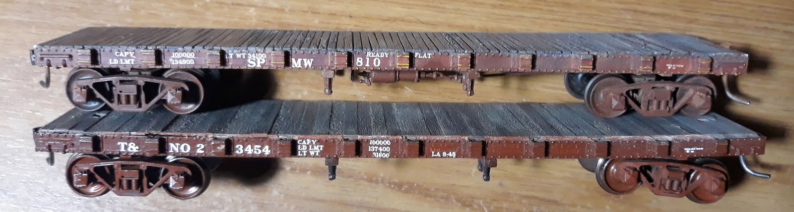 |
| SPMW 810 "Ready Flat" and T&NO 23454, both F-50-7 class kitbashes from Walthers-TM 42ft flatcars. |
The SP made interesting cars during WWI with the restrictions on large steel parts, such as the centersill beams. Two classes went back to using truss rods on an all-steel flatcar construction. The cars differed from earlier wood truss rod designs from 25+ years before, in having six truss rods to handle the 50-ton capacity of the body. Some cars were given old second-hand trucks rated at 40-tons. Later these F-40-6/7 class cars were upgraded with 50-ton trucks and reclassified as F-50-6 or F-50-7.
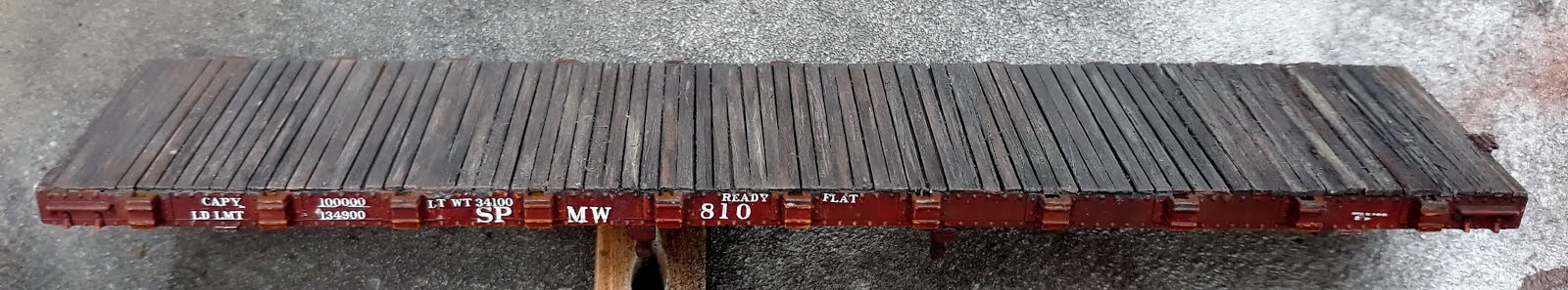
SPMW 810 - Ready Flat
I first started with a Walthers model which has a steel weight in it, no underframe. The original model has deck board detail which is flush with the top of the steel sides, so basically no side detail to the deck boards.
 |
| Starting point of SPMW 810 with Evergreen Styrene strips for the deck. |
I decided to add a new deck made from styrene 2x6 (0.020"x0.060") strip. Unfortunately, I ran out about 85% of the way through the deck installation. I finished it with scale 2"x6" strip wood.
 |
| I scribed the deck to help rough up the painted surface so the liquid glue will make a good bond with the styrene. |
Gaps were left between the boards to accent that the deck is old and wearing out. The boards are then weathered with my standard deck weathering tricks, distressing the boards with razor saw, scribe, and Xacto blades. Then painting the deck with variations in colors, etc.
The car should be 51" or 0.585" height. I measured the height of the car to the top of the deck to the bottom of the bolster and worked out that I needed to shorten the bolster tubes to 0.300".
 |
| SPMW 810 with plastic and wooden deck added and painted. - Wood strips at the right. |
I decalled the SPMW 810 with extra decals left over from building an OwlMtModels F-50-5/8/9/10/12 class car. The OMM 1210 F-50-class decal set could also be used.
Conversion to Steel Truss-Rod Underframe
These are the basic mechanical dimensions that I researched from the 1950 ORER. Measuring the deck, over the boards, to the rail, subtracting the rail to bolster height on the KD-573 trucks.
Deck height 51" = 0.585"
Bolster-Deck 0.300"
Kadee-573 "Vulcan" Trucks with IMRC 33" Wheels
The coupler mounting screw holes were already drilled from when I last worked on this car about 15 years ago. I mounted KD-150 (scale head, whisker spring) couplers on the car.
The new centersill beams are made from 0.040"x0.040" styrene strips, totaling 0.285" over the outside of the frames. This structure connects the two coupler boxes and pass outside the bolster tubes.
 |
| SPMW 810 with the new underframe of steel beams with queenposts. KD Vulcan Trucks are being fitted. |
Two cross 0.040"x0.110" strips are placed 2.275" in from each end and form the spacers to mount the MDC/Roundhouse queenposts to. Unfortunately, I don't have any 6-Queenposts available, so on these models I'm using the old stand-by MDC parts from my kitbashing box. I've reached the point, if I want to draw 6-post queenposts, then it will lead me to designing the whole F-50-7 car in the computer, so it makes the recycling of this older model pointless.
New bolsters are built from 0.020"x 0.080" strip styrene bridging from the new centersills to the outer sidesills. The prototype cars do have their bolsters exposed below the sidesills, so no need to hide these parts.
Three strips of 0.040"x0.040" are placed as shown in the photo to support the extra second hand K-brakes off an OMM F-50-series flatcar
I used a spare ratchet-&-pawl molding from an OwlMtModels F-50-series flatcar to make the top of the handbrake bracket.
In Closing
I plan to do future posts on the completion of SPMW 810 and work on the T&NO 23454 revenue flatcar.
Jason Hill
Related Articles:
Freight Cars - SP Flatcars - Overview
Modeling an MOW Supply Train (Part 1)
No comments:
Post a Comment
Please identify yourself at the end of your message. Please keep comments relevant to the post or questions to me directly.
All comments are moderated and must be approved, so give me a bit of time to approve them.
No random solicitation in comments. Spamming and phishing comments will be deleted or not allowed to post.