

Newly found Fairchild Aerial Survey 1944 photo of Owenyo! (West at the top, North to the right)
The most complicated section to construct I believe will be the stacked modules of Owenyo and Mojave staging yard directly below it. I think Owenyo yard can be built easily enough as three modules and then as the layout expands around the room, which will allow me to start 'playing' with Owenyo first to keep the interest up in the project. Though, the last post certainly challenges my interest in not focusing on the new shiny discoveries about Little Lake!
 |
| Owenyo and Mojave yard stacked in 3D render of the layout before newest changes to the far corner at Little Lake. |
Mojave likewise will be built as a set of three modules which will then stack under the Owenyo modules. These two modular yards will be removable from the wall, so the construction and mounting of the Owenyo modules before construction of the Mojave modules shouldn't pose a problem logistically. That said, I do plan to have the Mojave modules coming very shortly after the Owenyo modules are cut out.
One of the main challenges of the Owenyo module specifically is going to be keeping it to a total thickness of less than 2", as the planned rail-to-rail vertical separation is only going to be in the ball park of 5" between Owenyo and Mojave. Keeping 3" vertical clearance is enough for the trains, but as I experimented with recently, 4" is definitely better as I'll have room for the back of my hand over the boxcars in Mojave yard to rerail things! This will require nominal 1" thick layout at Owenyo or increasing the already rather stiff 1.5% grade, which may have detrimental effects to the tonnage rating of the Mk-2/4, which is planned to be my regular engine for the local pulling 10-14 cars to Owenyo.
Testing the 24" Radius for the Owenyo Wye
 |
| GoogleMaps view of Owenyo in 2021, North to the Right, scale showing 200ft. |
Looking at the GoogleMaps view of Owenyo above and my track plan below... the proportions are about right, but probably shrunk by about 30-50%.
 |
| CAD drawing showing the dump trestle at far left - 1-13-2021 version, North to the Right. |
The NG dump trestle in the lower left of the photo can still be made out with the footings of the trestle still there. The straight SG section in the pit is about 275ft long, scaling the photo with my calipers. 275ft is about six standard GS gondolas long.
 |
| Owenyo's SPNG transfer trestle pit still visible. North to the right, NG from Right, SG exiting to the left. Scale 50ft |
My model's length can be about 28" long, or about 200 feet, about four and a half GS gondolas long. So my regular local will work about four gondolas instead of a max of six each trip. Not too bad getting 2/3s full size considering I have to jam in into the corner there. The prototype SG also exits Owenyo on a curve, with the spur to the trestle dump flaring away from the main before swinging back, so that's not very far off either.
|
| Fairchild Aerial Survey 1944 photo of Owenyo, West at the top, North to the right. |
I started by checking the curves that my largest planned engines will need. This will be a Balboa Mk-5/6 with Sunset 120-C-2 tender (SP 3266) and a Sunset Mk-2/4 class with a 120-SC-series whaleback tender (SP 3203), or Sunset 120-C-2 tender (SP 3207/8).
 |
| Cardstock being marked as a radius tool for 24", 24.25", 25", 25.25", 26" and 26.25" curves to test. |
I started by making a line down a length of cardstock, about an inch from the edge. Then marked a center point about an inch in from the end. Measurements were then made to the various radii that I plan to need on the layout. These started with 24" and 24-1/4" radius. A hole was drilled with a hand pinvise at the center and radii points. The center hole then had a screw punched through, which will be screwed to the center of the arc point. The radii points were also drilled so that a pencil, pen or marker could fit through and trace the arc.
 |
| Code 83 Atlas Flex track being shaped and temporarily spiked at 24" curve. |
A piece of Code 83 Atlas flex track was then temporarily layed on the small sheet of 2x4ft MDF that I have with small ME spikes. This formed a 24" curve for testing. The Balboa Mk-5/6 with 63" drivers could negotiate the curve with out any issues. The Sunset Mk-2/4 with the smaller 57" drivers and shorter wheelbase, but still the same length frame caused the cab to hang out farther. Also the Sunset model had an overflow pipe from the injectors which dropped down the outside of the firebox right over the front edge of the trailing truck. This caused fouling of the trailing truck and forced it to derail.
 |
| Test curve set up to 25" to test Balboa Mk-5/6 and Sunset Mk-2/4. These engines are analog still, so an MRC 1300 power supply is used to be sure they don't bind up on the curves. |
I removed the flex track and remarked the arc at 25" radius. This time the Sunset Mk-2/4 had no problems, but it was still pretty tight clearance on the detail piping. After this test, I've decided that my minimum curves will be 26" radius, just to push the curve well above the absolute minimums.
 |
| CAD model, updated Jan 29, 2021 with 26" curves. |
The change from 24" to 26" minimum radius on my secondary trackage and the wye at Owenyo really only effects the west switch of the wye moving west a few inches, the tail of the wye extending into the room a bit more when it's installed, and the NG dump trestle alignment shifts slightly. The spur at Bartlett also changes, but I'll get to that in a little bit.
Construction Material Changes
Playing with Laying Out Owenyo on the Pink Foam
 |
| SP 3259, a Balboa Mk-5/6 with 120-C-2 tender checking the North Tail of the wye for clearance. |
Just for fun I plopped SP 3259, a Balboa Mike, on the north tail of the wye at Owenyo to check the clearance of where I expect the headblock of the switch will land. No problems here. The Sunset Mk-2/4 (3203) will be within a fraction of an inch of the same length.
 |
| "West" end of Owenyo #1 sheet marked out in pink foam for track centers. |
Laying out the track centers went pretty quickly with a Sharpie... just don't make any mistakes! However, while doing my first round of laying out track centers, I rethought the idea of using the track directly on the foam. Especially in the areas where I'm planning to have a large number of hand-built switches, which I intend to use ME spikes to fix the rails in place on individual wood ties. This form of hand-laid switches really require spline roadbeds or homosite-type pressed paper sheets to hold the spikes.
Switching to 1/4" MDF sheet for Owenyo
 |
| 4x8ft sheet of 1/4" MDF material for laying out the roadbeds for Owenyo. |
I have a 4x8 sheet of 1/4" MDF, which should hold the spikes well. So I have transferred the track centers for a narrower version of Owenyo to the MDF sheet. Here's a few more shots of this plan.
 |
| View of Owenyo #1 panel closer, and reversed Owenyo #2 panel middle. |
Unfortunately the CSRM Library hasn't responded to emails in several weeks, so it appears that I won't be able to get the actual ValMaps from there, which I know they have. Sad times. So I'm guessing that the track centers at Owenyo are the normal distance (for 1910) of 13ft 0in. This is easily marked with a scale rule and then track centers are marked against the straight edge with a mechanical pencil. The cheap Bic ones work fine for this.
 |
| Overview of east end of Owenyo #1 panel |
The Standard Gauge transfer pit will have to be cut into a tongue and depressed into the area below the MDF. Foam will be used to fill up the dirt slopes around it.
"PT" or Point Tangent is the natural point at which the diverging centerline for the switch meets the 'normal' route. "PF" or Point Frog is the point at which the diverging route's centerline (CL) and the normal route's CL cross at the standard wheel gauge. This point can vary somewhat to suit each switches exact alignment, but it's a good reference point. The Headblock or "HB" is where the switch points will be located and the point bar will connect them to the switch stand. Again the HB can move several scale feet, which will change the amount of easement the switch has in it.
I'm used to building No.7 switches, with a 7:1 run over side-step, but as I'll be building some special non-symetrical wye and some No.5 switches, I'll probably be adjusting the basic dimensions somewhat to help operations through the special switches. The standard No.7s I'll be building to the LMRC club standards to insure operations of equipment that I'm testing on this layout before going to the club for service.
|
| CAD model, updated Jan 29, 2021 with 26" curves. Panels numbered East to West 1, 2, 3. |
Above is the current track plan for Owenyo. At the right is panel #1, middle #2, and at left #3. On the MDF sheet the wye is cut off very close to the line of company dwellings inside the wye to save on MDF material. The rest of the wye will be built from another section of MDF to fit the curves. Panel #2 is rotated 180 degrees and is placed along the north side of Panel #1 in the progress photos in this post.
 |
| Owenyo, 1944 - aligned as in my CAD models - North is off to the right side. - Fairchild Aerial Survey |
I have not yet decided if the rest of this sheet of MDF will be cut into structural strips to frame the modules or if I'll use the rest of the sheet to form the three modules for Mojave. Also in question is if I'll use the MDF to form a support along the wall, which will support the two levels of the layout as a unit. More to think about.
 |
| Overview of Owenyo Panels 1 & 2 layed out on MDF board |
I plan to have Owenyo #1 Panel (east end) just cover the whole width of the tracks and the sub-base of the transfer platforms.
 |
| Owenyo #2 panel |
I'm changing my plan of using all No.7 switches and including a couple of No.5s, including this one on the Owenyo Team Track stub, which will pretty much never have a larger engine than the Mk-2/4/6 trying to operate on it.
 |
| Owenyo #1 Team gantry crane with 40ft F-50-flatcar on wide centers. Boxcars are on Oweny #2 panel |
Originally, I left plenty of room for the S-curves to get to the gantry crane track, which has about 1" offseting to wider track centers from the main track. However, after laying it out full size, I don't think it needs nearly as much room as I gave it, so I shortened the each S-curve by 1.5", which will give me 3" more length for the main transfer platforms at Owenyo. I'm biasing this extra 3" towards the east end where I really shorted the platform that is between the crane and the transfer pit spur.
 |
| Owenyo #1 west wye switch at bottom, Owenyo #2 team track and stub mid-photo. |
The above photo shows the west switch of the wye on #1 panel, which moved about 4" westward (left) to allow for the larger size of the radii on the wye. The boxcars are located on the long transfer platform on the #2 panel team track, with the tank car on the short stub track. Still not sure exactly what that track was used for. The right most boxcar would be lined up for the conveyor loader system from the NG. Not sure exactly what commodites were transferred through that system, but it looks like it the chute on the standard gauge side would allow gravity loading into boxcar doors, such as a grain loader. Not sure of the NG was actually exporting grain or if it was being used for pearlite or something in the 1959 photos.
 |
| SP 3259 sitting on bare MDF board with a boxcar. Westward at Owenyo panel #2, #1 foreground. |
SP 3259 sits, point westward on the main track on the Owenyo panel #2, this will be roughly the middle of Owenyo Yard when the modules are cut out and recombined into the final arrangement. The heavy "CUT" marks show where the modules will be seperated. This will also be the 'normal' viewing side for the Owenyo Yard modules. It should be interesting to have these modules semi-removable, which could allow me to pull them out for photography or someday trips to train shows!
I've left plenty of room between the Standard Gauge and the NG side of the modules. I need to do some more scaling of exactly how wide I think the transfer decks were, as I may end up being able to put in the closest NG track before it hits the wall. While I still don't think I'll have enough room for the NG to be functional, i.e. switches, runaround, contiguous track from one end of the module to the other, etc. I may have enough room to have a string of SPNG boxcars along the wall.
I've left plenty of room between the Standard Gauge and the NG side of the modules. I need to do some more scaling of exactly how wide I think the transfer decks were, as I may end up being able to put in the closest NG track before it hits the wall. While I still don't think I'll have enough room for the NG to be functional, i.e. switches, runaround, contiguous track from one end of the module to the other, etc. I may have enough room to have a string of SPNG boxcars along the wall.
So Where's the Foam Going?
The foam will still be used for land forms at Little Lake especially to get the vertical components of the road dipping below grade and the railroad's elevated fills in town. The foam will also be useful around the two depressed track areas at Owenyo (NG dump trestle and SG transfer pit) to form the sloping pits.
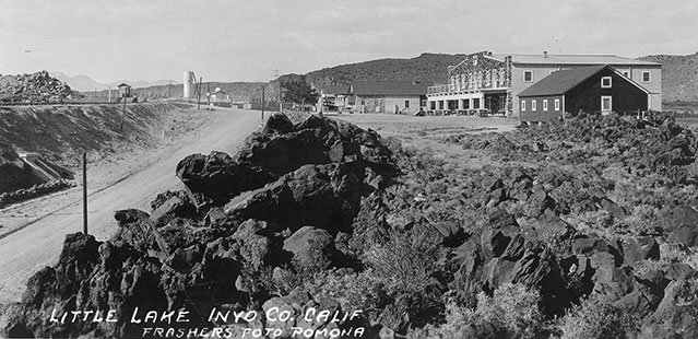 |
| Looking North at Little Lake with SP tracks on the fill to the left and the Hotel at the right. Look at the vertical changes in the terrain forms and the basaltic lava in the foreground! - owensvalleyhistory.com |
Notice in the photo above the large gasoline tank and pump house which is next to the ore dump spur. I believe a number of these photos are taken before the highway was put across the lake on its own fill, and at this point the main road crosses the tracks and runs up the west side of the SP mains past the company village. The 1944 Aerial Photo shows that the highway was put through parallel to the SP main track on the east side by 1944.
Little Lake will probably end up with a narrow strip of MDF with the right-of-way on, surrounded by the foam forming higher and lower terrain forms around it. The major depressions being where the old-road starts dropping away from the RR at the west end of town and a couple of places where the railroad is on fills. There are a couple of rock outcroppings of basaltic lava very close to the track, on the aisle side on the model, which I may be able to model. The wider areas of the corner and the nook next to the bookcase will need to be used for the Hotel, etc and the company village will probably be over my desk.
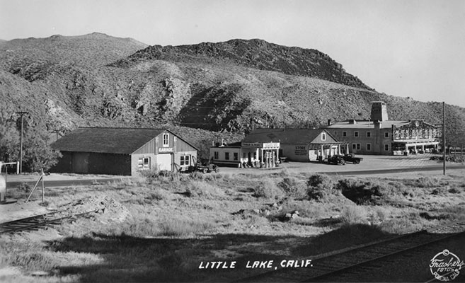 |
| Little Lake from the main line, foreground. Notice the ore spur at left and some edges of the infrastructure related to the gasoline tanks possibly at far left. - owensvalleyhistory.com |
I'm sure some selective compression will need to be used to get everything to fit into those areas. I also expect that the track may have to be pulled slightly away from the wall to make room for the siding, building flats against the wall, and the old road between the two. This should be an interesting challenge.
Revising the CAD Track Plan... Again!
I'll be going back to the CAD model as I redefine the Little Lake scene and shift the track centers around somewhat. Pulling the track away from the north wall and straightening it slightly, will reduce the length of run, not allowing quite as much drop between Owenyo and Mojave staging yard. This plus the desire to get a little more hand room over the cars in the staging may result in needing to increase the grade somewhat. Once nice thing about building the Owenyo modules... I can do a tonnage test of the Mk-2/4/6s once I have some track which can be inclined to do it on!
 |
| Town of Little Lake during my modeling era, approximately. Google Maps base image 2021. |
 |
| Little Lake, 1944 Fairchild Aerial Survey - with my notations |
 |
| Northeast corner of my shop space over the lathe and desk. |
This track plan is from the Linnie + Little Lake concept from Jan 24, 2021. From the study of the Little Lake town and company village, which I'd like to model in a more complete form than would be allowed with the original design.
The switch for the spur at Linnie in the NE corner will be pushed south and form the west siding switch for Little Lake. This will require the whole main track to be pushed south several inches, possibly as much as 6-8" to get the needed space for the ore dump spur and old highway to be in the scene too, thus allowing the structures to at least be 'building fronts' along the wall. The layout over the work table will probably bump out to allow for the SPMW Boarding car spur and company village's carbodies, which should add some interest there.
One nice thing about the desk and upper organizing shelves being where it is, will be that it will help create a natural break to the scene at the bookcase. I'll be able to put a curved backdrop into the corner of the bookcase and the North wall, which should create a good feel for a viewer standing in the east half of the shop. The scene at Bartlett to the west of the desk will then have good separation and prevent a viewer from seeing the other scene, which are prototypically 41 miles apart!
Jason Hill
In Closing
 |
| CAD drafting overlay of the 1944 Fairchild Aerial Survey photo. 1959 Company Village added. |
Obviously, I'm still working on the designs. In the next blog post I'll be returning to looking at some of the details related to Owenyo, which I have recently found more photos of on the Owens Valley History website. These photos when properly looked at in close detail will reveal considerations relating to the spacing of the tracks, compression factors, and other details of the relations between the design elements. As the construction of the Owenyo section is about to commence, I'd rather slow down slightly to get the fine positions worked out before I start gluing track down and hand spiking switches!
Jason Hill
Related Articles:
SP Jawbone Branch (Part 1) - Concept
SP Jawbone Branch (Part 2) - Researching and Changing of the Plan
SP Jawbone Branch (Part 3) - Consists and More Bartlett Research
SP Jawbone Branch (Part 4) - Freight Car Roster
SP Jawbone Branch (Part 5) - Pulling the Trigger (Buying the materials for the benchwork)
SP Jawbone Branch (Part 6) - Q&A Continuing Design Tweaks - Working out the logistics for the staging yards other details.
SP Jawbone Branch (Part 7) - Film & Construction Begins - Historic movie film clip of Owenyo Local and starting construction of the layout.
SP Jawbone Branch (Part 8) - Little Lake Grows - More research materials have surfaced for my modeling of Little Lake
SP Jawbone Branch (Part 8) - Little Lake Grows - More research materials have surfaced for my modeling of Little Lake
No comments:
Post a Comment
Please identify yourself at the end of your message. Please keep comments relevant to the post or questions to me directly.
All comments are moderated and must be approved, so give me a bit of time to approve them.
No random solicitation in comments. Spamming and phishing comments will be deleted or not allowed to post.