
 |
| SP 3203 doing some radius testing on the Owenyo wye. - I still haven't scratch-built the tender yet, so I can't really run this engine without a clip-lead leash supplying left-rail power yet. |
Construction is pivoting to get some operations going now that the LED lighting is working. Before the last year break in progress, I'd been pushing to get the switches working. The really nice scale switch stands and linkages are still being worked on in my mind and I'll probably need to build a test switch on a piece of scrap material to proof that design. However, for now I decided to go with Caboose Industries ground throws, which are over-scale, but at least will make the switches functional and keep the momentum up on layout progress.
Ground Throws
 |
| Notice the forest of switch stands in front of SP 3203 Owenyo - Eddie Sims Collection |
The SP switch standards call for single headblocks on non-powered switches, so that will make mounting the Caboose Industries ground throws a little more challenging. Let's look at how I mount the ground throws.
 |
| A hole is made in the switch throw-bar with a 0.052" drill to accept the pin on the ground throw. |
The throw-bar needs a hole drilled for the pin that is in the end of the 205S ground throw. This version of the ground throw is sprung to allow over-center camming of the control arm down to the horizontal position, which is good to keep tension in the switch points.
Once the hole is drilled in the throw-bar, I can center the points between the stock rails and also the lever on a ground throw. The ground throw pin is then inserted into the throw-bar and centered up with the slide parallel to the headblock. I use a mechanical pencil to mark the extended center point of the two mounting holes in the ground throw base on to the layout.
The way this works out with the 16" wide headblocks, it puts one ground throw base hole just outside the headblock (away from the frog) and the other out in the open, which will ideally get a spacing pillow block to keep the ground throw base level.
 |
| Installed Caboose Industries S205 ground throw, lacking the non-headblock side pillow block in this photo. |
I use a metal straight-edge (ruler) to connect the extended center point marks, forming an X. Small holes are drilled at the marked center points. Small self-tapping screws are used to mount the ground throws.
Operations Start!
 |
| A very great photo standing in the main east Owenyo switch, at left is a switchstand with a yellow target. - Alden Armstrong photo circa 1959. |
The prototype switch stands have red or yellow painted SP standard round targets. Interesting to notice that the main track switch and the switch to the wye have guard rails, while the switch to the house track is using a self-guarding frog and no guard rails. I'm building my model with all plain frogs which are not self-guarding. There will also be a lot of fun filling in the dirt around the track when I get to that stage, but for now back to the ground throws.
Target Color?
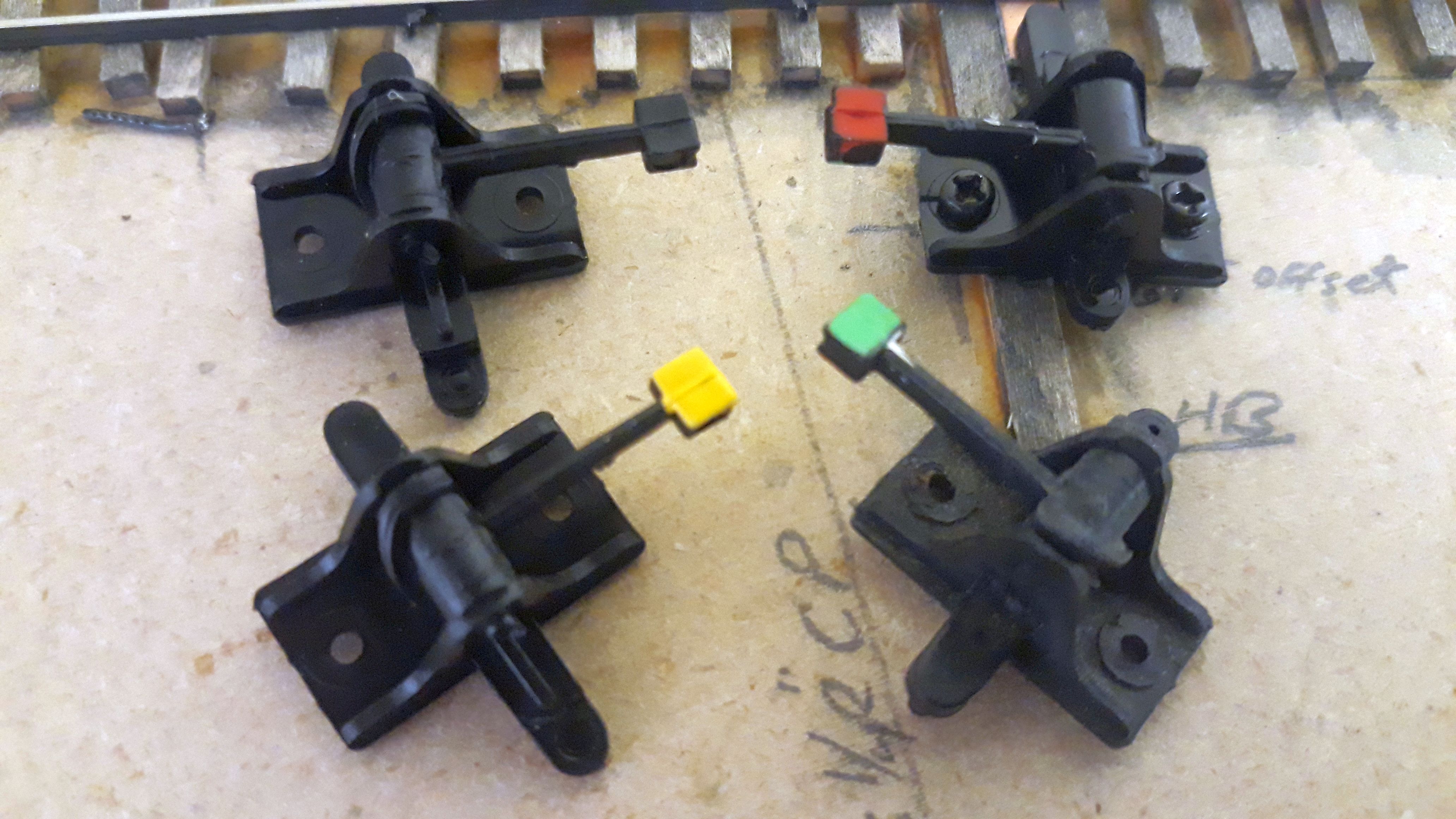 |
| Caboose Industries S205 ground throws (stock top left) with "targets" painted on handles (other three). |
As this version of the Caboose Industries ground throw do not have options for high targets, I resorted to painting the tops of the ground throw levers to represent the route and normal position of the switch:
Green indicates normal route, and max track speed allowed.
Yellow indicates normal position and restricted speed.
Red indicates reversed switch and obviously restricted speed.
Control System & Engines?
 |
| East Owenyo with ground throws installed. |
So with the majority of the east end switches at Owenyo functioning now, attention is turned back to getting an engine running. I haven't set up the NCE PowerCab on the layout yet, but I do have a MRC 1370 analog DC power pack, which I've had as my test bench power supply to test engine's mechanisms before DCC installations. The LMRC club standards call for engines not to have the DC option enabled, so basically all LMRC assigned engines that I have at home shop right now really can't just be dropped onto the DC track and run. Also they are very finicky about using nearly 1/2 throttle to start to move and if you close the throttle too much, the chips shut down. So makes it very hard to do slow speed testing with a DCC chipped engine in analog power mode.
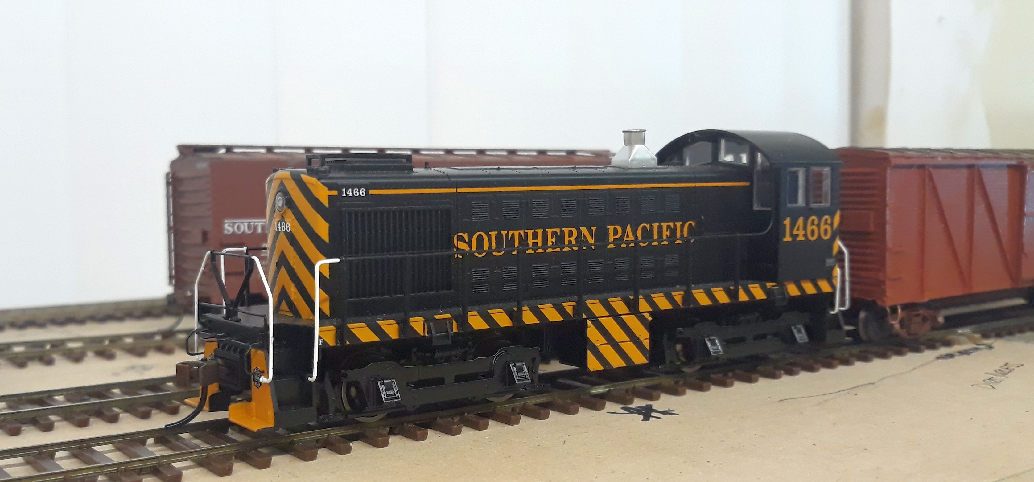 |
| A bit far from home SP 1466, an Alco S-4 switcher, tests the track work and electrical at Owenyo under basic DC analog control. |
I dug around in one of my boxes and found I still have an older Bachmann Alco S-4 SP switcher which has not received a DCC chip yet. So I pulled it out of the box and started seeing if it was in good shape to use.
 |
| SP 1466 shoves 3 cars onto the east end tail track, showing there's only room for an Mk-2/4/5 or a small diesel and one car. |
Now the fun part of not yet building the #3 Owenyo module comes to light... The head space off the east-most switch at East Owenyo only gives a bit more length than an Mk-4's length with 120-C-6 or 120-SC-series tender. With the Alco S-4, this gives me one 40ft freight car length to shift between the Owenyo Siding/wye and the Main/House track. So operations are limited for now to testing and getting the switches dialed in.
Continuing Operations Paperwork Development
 |
| I moved all the station codes and station maps over to a new document to start an ETT/SI page. Still in development. |
This is the next step in my switchlist and paperwork development for the Jawbone Branch. While I'd love to eventually put together an LMRC 1950s style prototypical Employe Time Table & Special Instructions, for now I'm just dumping most of this clerk research documentation, which doesn't directly fit into the ETT, but draws some information on stations and MPs from the ETT.
Obviously, Once I get the main grade profile built from Mojave staging up to Owenyo, then I'll be able to use the LMRC method of calculating engine ratings (Employe Timetable Ratings & Operations). Once those are established, I can build an engine ratings table for my ETT for the Jawbone Branch.
Obviously, Once I get the main grade profile built from Mojave staging up to Owenyo, then I'll be able to use the LMRC method of calculating engine ratings (Employe Timetable Ratings & Operations). Once those are established, I can build an engine ratings table for my ETT for the Jawbone Branch.
In Closing
I'm going to wrap up this post at this point. The next major steps that need to happen is dismantling the module stacks of Owenyo to install the LED lighting for the staging yard underneath and Mojave to wire the tracks for the staging yard to get working.
Once those two steps are done, then construction of the #3 West Owenyo module which will allow some expansion of switching operations at Owenyo. I should also plan to build the Owenyo-Bartlett "Across door bridge" #4 module as well, to start gaining more switching lead length to work Owenyo proper.
 |
| Next big project to build - West end of Owenyo CAD 3d rendering. Jawbone Branch #3 Module. |
 |
| Early Mojave Yard staging design. Jan 13, 2021 design. |
Along the construction of Owenyo #3, the eastern module of Mojave staging yard is needed to be built, so that I won't need to keep lifting off the Owenyo modules to work on Mojave. I may also install a strip of LED lighting under the staging yard for the work bench to have even lighting.
Jason Hill
Related Articles:
SP Jawbone Branch (Part 33) - Expanding Operations - Mojave, Station Numbers, & Switchlists?
SP Jawbone Branch (Part 23) - Switch Parts & LMRC Switch Standards - Laying Switches at Owenyo
SP Jawbone Branch (Part 27) - Finishing Up East Owenyo Switches - Putting the switches together... need switchstands.
As long as you are bending things and not using tall switch stands, you might as well use two headblocks and make it a little easier.
ReplyDeleteI still plan to use high stands, I just need to work out exactly how I'm going to do it. These are "for now" and nothing involved in the installation damages the existing single headblocks.
DeleteAre you going to be able to avoid the temptation of painting a Halloween Alco?
ReplyDeleteYes... very easy to avoid doing that, as it would push me at least 3-4 years past my modeling era.
DeleteFrom previous photos I can see that you have a fascia on your layout. Have you considered operating the switches using push-rods mounted under the layout and extending through the fascia, and using a slide switch to both lock the throw-bar and power the frog? Then either simply installing scale sized dummy switch stands, or possibly stands which pivot in response to the push-rod movement?
ReplyDeleteYes, yes, and yes. Have I had the time to build a mockup and a test switch to check it all before I start punching holes in the existing layout? No, I haven't. However, I have had most of the supplies to do so, including the micro slide switches to power the frogs and the DTA SP style switch stands, for more than the last year. I bought those parts when I bought the track and supplies back in Feb 2021.
DeleteThe Caboose Industry stands are to get the layout up and running and to keep the interest high on the project. I'll probably keep them in the staging yard.